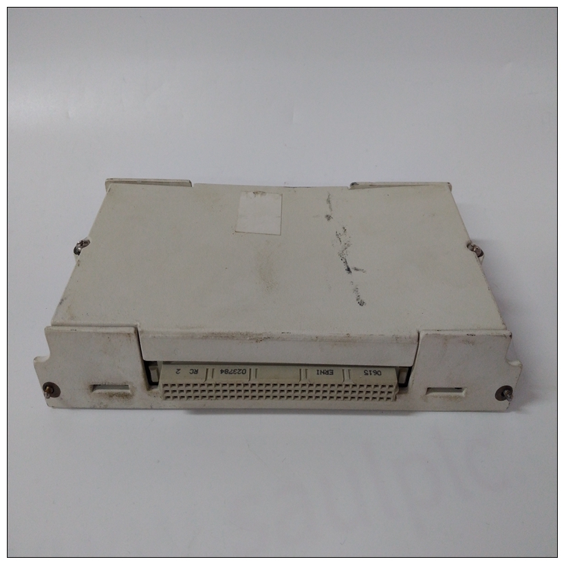
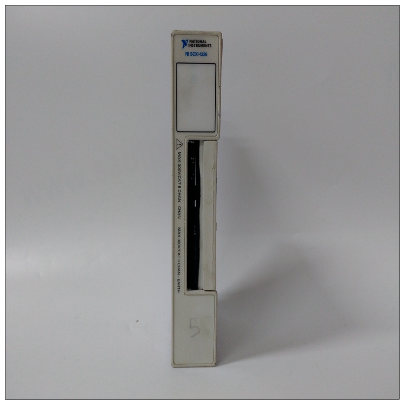
NI SCXI-1326電流輸出模塊,SCXI-1326產品顏色
IP總線時鐘頭(J11)J11選擇IP總線時鐘的速度。IP總線時鐘速度可能為8MHz或本地總線時鐘的速度(MC68060為30MHz,MC68LC060為32MHz)。默認出廠配置具有J11引腳1和2上安裝的跳線,表示8MHz時鐘。如果跨接導線安裝在J11針腳2和3之間,則IP總線時鐘速度與MC68060或MC68LC060總線時鐘的速度匹配(30/32MHz),從而允許IP模塊與30/32MHz MPU一起運行。


NI SCXI-1326電流輸出模塊無論設置是8MHz還是30/32MHz,所有IP端口都在同一個RAM備用電源選擇標頭(J14)上運行收割臺J14確定車載靜態RAM備用電源的來源在MVME172LX上。以下備用電源配置可用于車載SRAM通過收割臺J14。在工廠配置中,VMEbus+5V備用電壓作為一次和二次電源車載電池已斷開)。速度IP總線選通選擇標題(J18)一些IP總線實現使用選通? 信號(針腳46)組件從IP2芯片到IP模塊的輸入。其他IP接口需要閘門應斷開。在J18針腳1和2之間安裝跨接導線后,可編程頻率源連接至選通管? IP總線上的信號。提到MVME172嵌入式控制器中的IP2芯片編程部分其他信息的程序員參考指南。如果從J18上拆下跨接導線,則選通線可用于IP模塊之間的邊帶消息類型。閃光燈? 信號不是連接到板上的任何活動設備,但它可能連接到上拉電阻器。IP DMA偵聽跳線(J19)J19定義了當IP DMA控制器是本地總線主控。J19針腳1和2啟用/禁用Snoop控制MC68060處理器上的信號(引腳3-4在MVME172LX板)對于MVME172LX,短路引腳1-2可實現監聽。留下別針1-2斷開連接(出廠配置)禁止窺探。具有
啟用偵聽后,將驅動發送至MC68060處理器的偵聽信號在IP DMA操作期間為低。
IP Bus Clock Header (J11)
J11 selects the speed of the IP bus clock. The IP bus clock speed may be
either 8MHz or the speed of the local bus clock (30MHz for the MC68060,
32MHz for the MC68LC060). The default factory configuration has a
jumper installed on J11 pins 1 and 2, denoting an 8MHz clock.
If the jumper is installed on J11 between pins 2 and 3, the IP bus clock
speed matches that of the MC68060 or MC68LC060 bus clock
(30/32MHz), thus allowing the IP module to run with a 30/32MHz MPU.
Whether the setting is 8MHz or 30/32MHz, all IP ports operate at the sameSRAM Backup Power Source Select Header (J14)
Header J14 determines the source for onboard static RAM backup power
on the MVME172LX.
The following backup power configurations are available for onboard
SRAM through header J14. In the factory configuration, the VMEbus +5V
standby voltage serves as primary and secondary power source (the
onboard battery is disconnected).
speed.IP Bus Strobe Select Header (J18)
Some IP bus implementations make use of the Strobe? signal (pin 46) as
an input to the IP modules from the IP2 chip. Other IP interfaces require
that the strobe be disconnected.
With a jumper installed between J18 pins 1 and 2, a programmable
frequency source is connected to the Strobe? signal on the IP bus. Refer to
the IP2 chip programming section in the MVME172 Embedded Controller
Programmer’s Reference Guide for additional information.
If the jumper is removed from J18, the strobe line is available for a
sideband type of messaging between IP modules. The Strobe? signal is not
connected to any active devices on the board, but it may be connected to a
pull-up resistor.IP DMA Snoop Jumper (J19)
J19 defines the state of the snoop control bus when an IP DMA controller
is local bus master. J19 pins 1 and 2 enable/disable the Snoop Control
signal on the MC68060 processor (pins 3-4 have no function on
MVME172LX boards)For the MVME172LX, shorting pins 1-2 enables snooping. Leaving pins
1-2 disconnected (the factory configuration) inhibits snooping. With
snooping enabled, the snoop signal to the MC68060 processor is driven
low during IP DMA operations.


