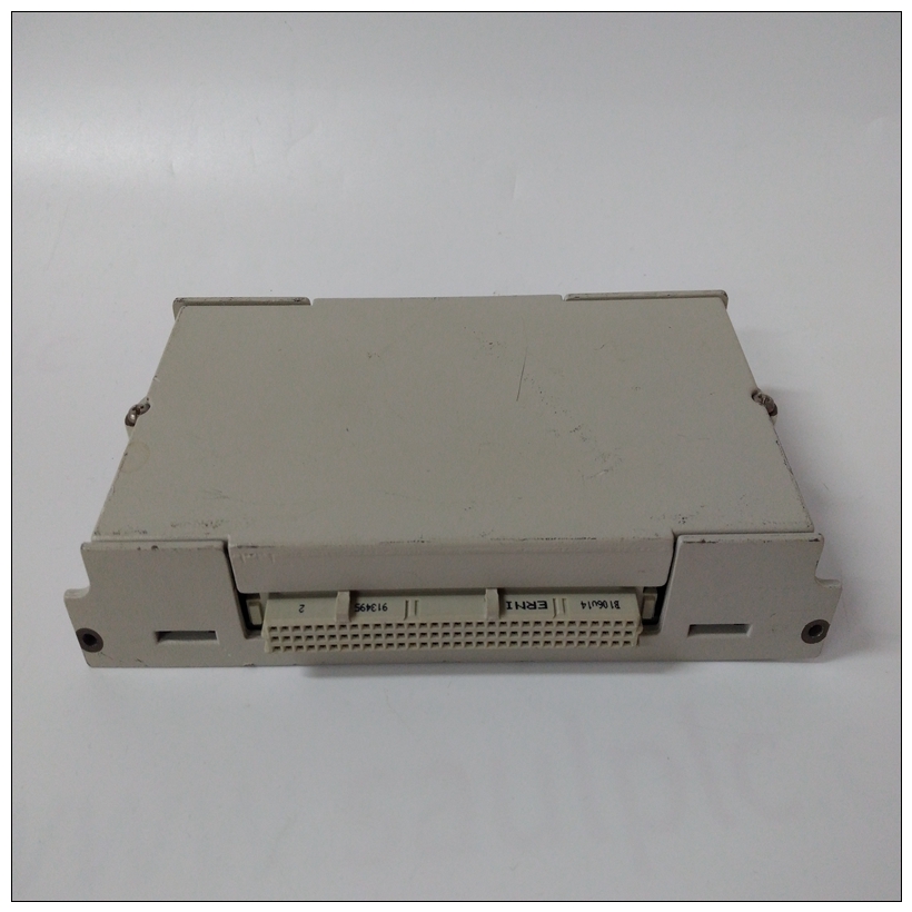
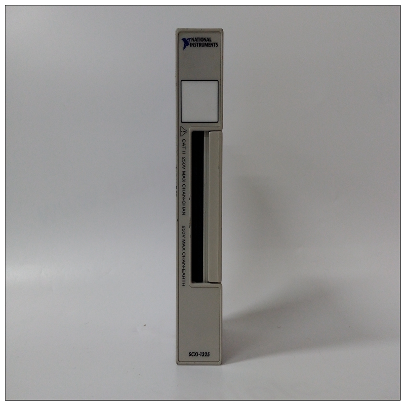
NI SCXI-1325電壓輸入模塊,SCXI-1325配置手冊
執行這些操作之前,請關閉系統電源程序。在打開前未能關閉電源外殼可能導致人身傷害或設備損壞設備危險電壓、電流和能級為存在于機箱中。上可能存在危險電壓即使在電源開關關閉時,電源開關端子也是如此。切勿在卸下蓋子的情況下操作系統。總是在給系統通電之前,請更換蓋子。準備董事會產生所需的配置并確保MVME172LX,您可能需要執行某些硬件修改安裝模塊之前。


NI SCXI-1325電壓輸入模塊MVME172LX提供了對大多數選項的軟件控制:通過在系統中安裝模塊后,在控制寄存器中設置位可以修改其配置。(描述了MVME172LX寄存器在第3章的ENV–Set環境和/或MVME172 VME中“相關”中列出的嵌入式控制器程序員參考指南附錄E中的“文件”)
然而,有些選項不是軟件可編程的。這些選項包括通過手動安裝或拆除收割臺跳線或基板上的接口模塊。MVME172LX配置圖1-1說明了跳線頭、連接器和MVME172LX上的各種其他組件。手動配置下表列出了MVME172LX上的跳線頭(帶有默認設置括在括號中)。系統控制器選擇標題(J1)MVME172LX在工廠配置為VMEbus系統控制器(即,跨接導線安裝在收割臺J1的針腳1和2之間)。拆下J1如果MVME172LX不是系統控制器,則跳線。請注意當MVME172LX用作系統控制器時,SCONLED亮起。注:MVME172s沒有可選的VMEbus接口(即。,如果沒有VMEchip2 ASIC),則可以安裝或在不影響正常操作的情況下移除
Turn the system’s power off before you perform these
procedures. Failure to turn the power off before opening the
enclosure can result in personal injury or damage to the
equipment. Hazardous voltage, current, and energy levels are
present in the chassis. Hazardous voltages may be present on
power switch terminals even when the power switch is off.
Never operate the system with the cover removed. Always
replace the cover before powering up the system.
Preparing the Board
To produce the desired configuration and ensure proper operation of the
MVME172LX, you may need to carry out certain hardware modifications
before installing the module.
The MVME172LX provides software control over most options: by
setting bits in control registers after installing the module in a system, you
can modify its configuration. (The MVME172LX registers are described
in Chapter 3 under ENV – Set Environment, and/or in the MVME172 VME
Embedded Controller Programmer's Reference Guide as listed in “Related
Documentation” in Appendix E.)
Some options, however, are not software-programmable. Such options are
controlled through manual installation or removal of header jumpers or
interface modules on the base board.
MVME172LX Configuration
Figure 1-1 illustrates the placement of the jumper headers, connectors, and
various other components on the MVME172LX. Manually configurable
jumper headers on the MVME172LX are listed in the following table (with
default settings enclosed in brackets).System Controller Select Header (J1)
The MVME172LX is factory-configured as a VMEbus system controller
(i.e., a jumper is installed across pins 1 and 2 of header J1). Remove the J1
jumper if the MVME172LX is not to be the system controller. Note that
when the MVME172LX is functioning as system controller, the SCON
LED is turned on.
Note On MVME172s without the optional VMEbus interface (i.e.,
with no VMEchip2 ASIC), the jumper may be installed or
removed without affecting normal operation


