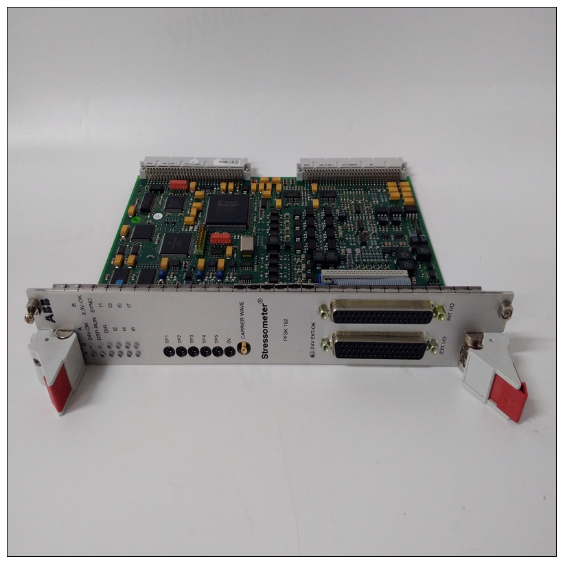
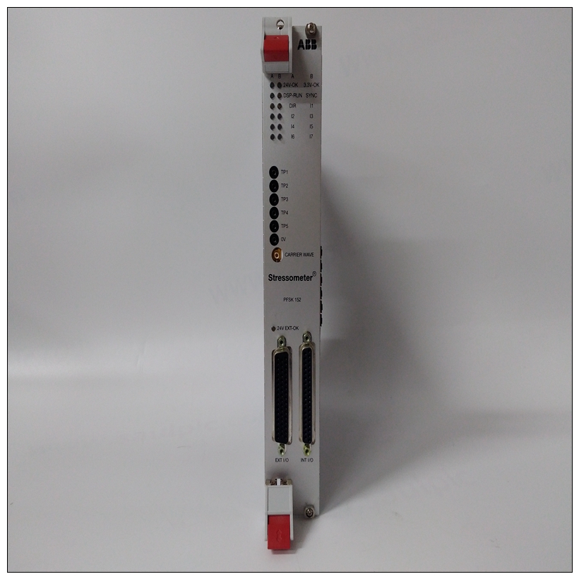
PFSK152 3BSE018877R2 3BSC980006R361模塊卡件
通常需要通過將CT連接到RTS或一些+12伏電源,如圖A-1所示的電阻器。
電流互感器也經常跨接至MC1488門,該門具有輸入接地(為此提供柵極)。
許多系統中使用的另一個信號是DCD。最初的目的該信號的目的是通知系統來自正在接收遠程調制解調器。該信號經常使用由軟件顯示信息,如承運人不在場幫助用戶診斷通信故障。顯然,如果系統正確設計為使用該信號,且未連接對于調制解調器,信號必須由上拉電阻器或閘門如上所述(見圖A-1)。許多調制解調器期望DTR高信號并發出DSR響應。


PFSK152 3BSE018877R2 3BSC980006R361模塊卡件軟件使用這些信號來幫助提示操作員關于可能的故障原因。有時使用DTR信號斷開電話電路以準備另一個自動呼叫這些信號是與所有人通信所必需的可能的調制解調器(見圖A-1)。示例配置圖A-1是一個良好的中間道路配置,幾乎始終有效。如果未從接收到CT和DCD信號調制解調器,跳線可以移動以人為提供需要的信號。圖A-2顯示了連接EIA-232-D連接器以啟用一種僅用三條線連接到基本終端的計算機。這是可行的,因為大多數終端都有DTR和RTS信號開啟,可用于拉起CT、DCD和DSR信號。可以使用其中兩個背靠背接線的連接器。在這個然而,在實現過程中,診斷消息可能會否則不會生成,因為所有握手都是繞過。此外,TX和RX線路可能必須交叉因為來自終端的發送是傳出的,但調制解調器上的發送線路是輸入信號。另一個需要考慮的問題是接地引腳的使用。有兩個標有GND的引腳。針腳7是信號接地,必須連接到遠程設備以完成電路。針腳1是底盤接地,但必須小心使用。機箱是通過中的綠色導線連接到電源接地電源線和必須連接到機箱才能進入符合電氣規范。
usually necessary to make CTS high by connecting it to RTS or to
some source of +12 volts such as the resistors shown in Figure A-1.
CTS is also frequently jumpered to an MC1488 gate which has its
inputs grounded (the gate is provided for this purpose).
Another signal used in many systems is DCD. The original purpose
of this signal was to inform the system that the carrier tone from the
distant modem was being received. This signal is frequently used
by the software to display a message such as CARRIER NOT PRESENT to
help the user diagnose failure to communicate. Obviously, if the
system is designed properly to use this signal and is not connected
to a modem, the signal must be provided by a pullup resistor or
gate as described above (see Figure A-1).
Many modems expect a DTR high signal and issue a DSR response.
These signals are used by software to help prompt the operator
about possible causes of trouble. The DTR signal is sometimes used
to disconnect the phone circuit in preparation for another automatic
call. These signals are necessary in order to communicate with all
possible modems (see Figure A-1).
Sample Configurations
Figure A-1 is a good middle-of-the-road configuration that almost
always works. If the CTS and DCD signals are not received from the
modem, the jumpers can be moved to artificially provide the
needed signal.Figure A-2 shows a way of wiring an EIA-232-D connector to enable
a computer to connect to a basic terminal with only three lines. This
is feasible because most terminals have DTR and RTS signals that
are ON, and which can be used to pull up the CTS, DCD, and DSR
signals.
Two of these connectors wired back-to-back can be used. In this
implementation, however, diagnostic messages that might
otherwise be generated do not occur because all the handshaking is
bypassed. In addition, the TX and RX lines may have to be crossed
since TX from a terminal is outgoing but the TX line on a modem is
an incoming signal.Another subject to consider is the use of ground pins. There are two
pins labeled GND. Pin 7 is the SIGNAL GROUND and must be
connected to the distant device to complete the circuit. Pin 1 is the
CHASSIS GROUND, but it must be used with care. The chassis is
connected to the power ground through the green wire in the
power cord and must be connected to the chassis to be in
compliance with the electrical code.


