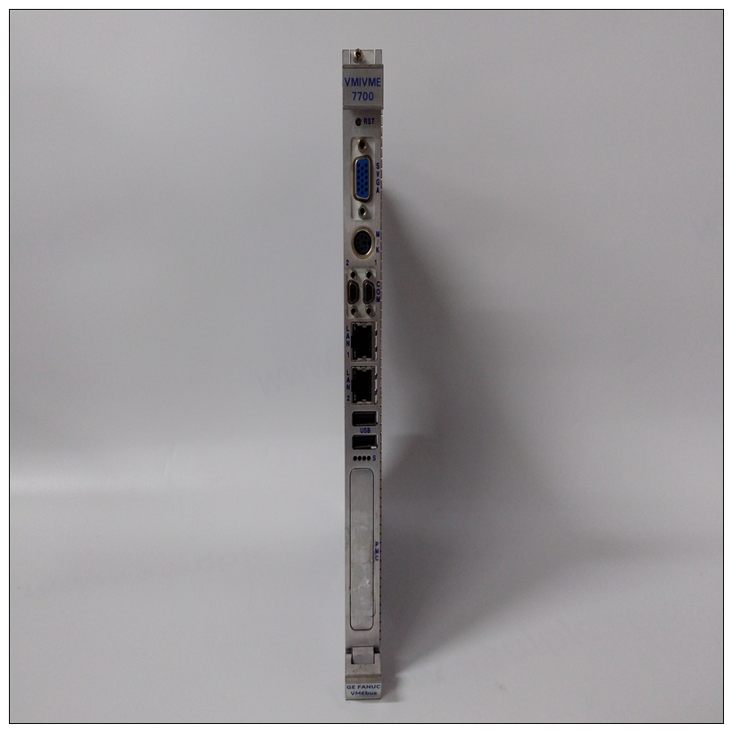
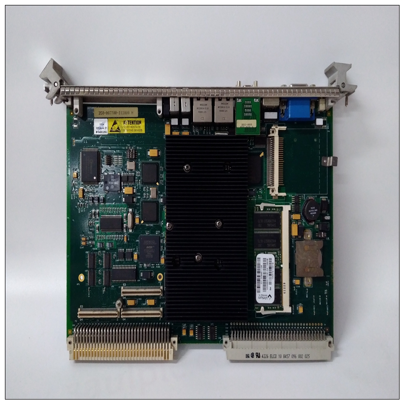
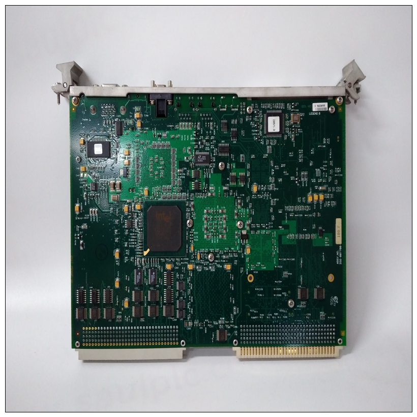
VMIVME-7700 350-007700-111000 H燃機卡件
此32位讀/寫寄存器指向物理DMA傳輸期間使用的地址和字節計數選擇表格模式時。表地址必須為長字對齊,因為位0和1始終為零。如果表地址位0或1集,它們被截斷,不會生成錯誤。這些位不受重置影響。有關表中的詳細信息,請參閱第5章住址數據地址寄存器該32位讀/寫寄存器指向物理地址,其中要傳輸數據。


VMIVME-7700 350-007700-111000 H燃機卡件數據只能傳輸到/從板載DRAM或VMEbus內存。這些位不受重置字節計數寄存器該32位讀/寫寄存器包含一個以位為單位的24位字節計數器0-23,第24-26位為3位功能代碼,第31位為鏈路位。這個字節計數器包含要傳輸的字節數。這個傳輸數據時使用功能代碼位。當設置為表條目,鏈路位表示DMA中有更多條目桌子該位在最后一個表條目中被清除。鏈接位僅為用于表格模式,從不由MC68030設置。這些位是不受重置影響。該16位讀/寫寄存器保存滴答定時器預加載值。當計數器達到$FFFF時,加載該值,如果啟用中斷后,生成中斷。運行時,計數器每6.25微秒遞增一次。以下內容應使用等式確定a的計數器值(n)時間t的周期性中斷,其中t以秒為單位。定時器可編程為每隔一段時間產生中斷在6.25微秒到0.4096秒之間。這些位不是受重置影響。定時器1計數器寄存器該16位讀取寄存器是滴答計數器的輸出。讀數為未與計數器更新同步。位設置和清除指令不應用于此中斷控制寄存器。因為中斷是通過向狀態位和狀態位寫入1清除為1表示掛起的中斷,讀修改寫序列可以清除掛起的中斷。
Table Address Register
This 32-bit read/write register points to a table of physical
addresses and byte counts that are used during DMA transfers
when table mode is selected. The table address must be longword
aligned because bits 0 and 1 are always zero. If the table address has
bit 0 or 1 set, they are truncated and no error is generated. These bits
are not affected by reset. Refer to Chapter 5 for details on Table
Address.Data Address Register
This 32-bit read/write register points to the physical address where
data is to be transferred. Data can only be transferred to/from
onboard DRAM or VMEbus memory. These bits are not affected by
resetByte Count Register
This 32-bit read/write register contains a 24-bit byte counter in bits
0-23, a 3-bit function code in bits 24-26, and a link bit in bit 31. The
byte counter contains the number of bytes to be transferred. The
function code bits are used when data is transferred. When set in a
table entry, the link bit indicates there are more entries in the DMA
table. This bit is cleared in the last table entry. The link bit is only
used in table mode and is never set by the MC68030. These bits are
not affected by reset.This 16-bit read/write register holds the tick timer preload value.
When the counter reaches $FFFF, it is loaded with this value and if
interrupts are enabled, an interrupt is generated. When running,
the counter is incremented every 6.25 microseconds. The following
equation should be used to determine the counter value (n) for a
periodic interrupt of time t where t is in seconds. The timer may be programmed to generate interrupts at intervals
between 6.25 microseconds and 0.4096 seconds. These bits are not
affected by reset.
Timer 1 Counter Register
This 16-bit read register is the output of the tick counter. Reads are
not synchronized with counter updates.Bit set and clear instructions should not be used on this
interrupt control register. Because an interrupt is
cleared by writing a 1 to the status bit and the status bit
is a 1 to indicate a pending interrupt, the read-modifywrite sequence may clear a pending interrupt.


