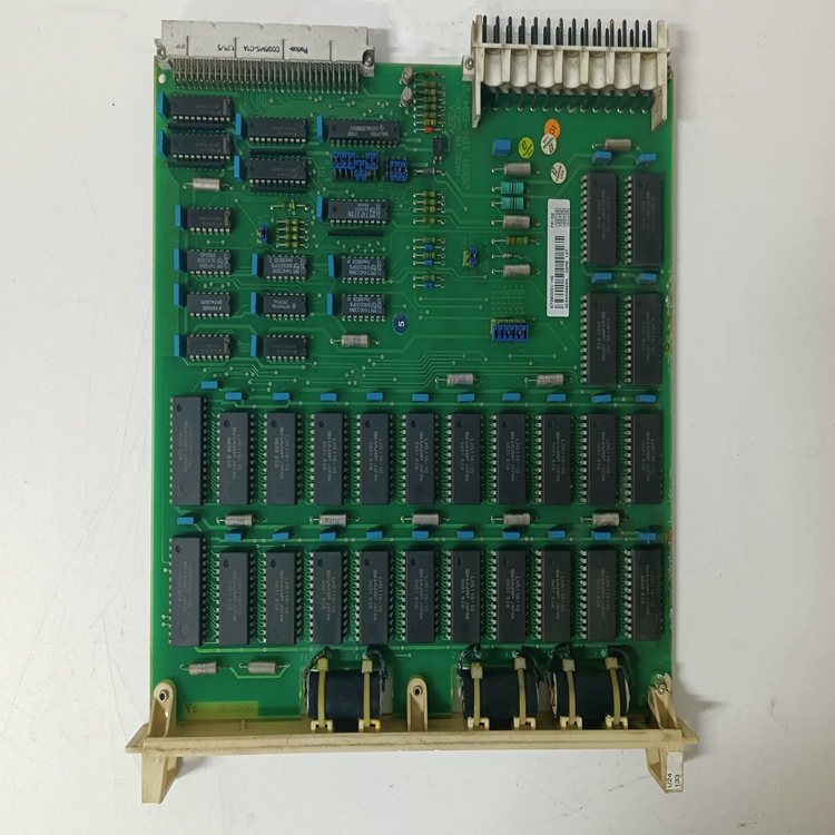
DCS系統DSMB179 57360001-MS模塊的操作DSMB 179
繼電器電路FA-M3的輸入/輸出點通常直接連接到外部設備。然而,在以下情況下,繼電器應放置在控制器的輸入/輸出點和外部設備之間:-控制器遠離外部設備,容易受到現場噪聲干擾。-控制器應連接至產生高壓噪聲的設備需要澄清其他控制線路之間關于處理各自信號的責任的關系需要包括一個手動操作電路,作為I/O設備故障的備用電路。聯鎖處理特定輸出時,需要聯鎖電路,例如不能同時打開的電機正反轉輸出。在這種情況下,安裝外部聯鎖電路可使兩個繼電器線圈的“b”觸點中的一個在通電時切斷另一個。圖A3.13顯示了聯鎖電路的示例。

輸出短路保護
如果連接到FA-M3輸出端子的任何負載短路,則會產生過多的短路電流,并且外部接線可能會燃燒或產生異常熱量。因此,通常在輸出電路中安裝保險絲,以確保短路負載情況下的安全,并將FA-M3的損壞降至最低。建議使用外部保險絲,尤其是對于沒有內置保險絲或短路保護器的輸出模塊。圖A3.12是配備輸出短路保護熔斷器的FA-M3的示例。請注意,這些保險絲并不用于保護內部輸出元件免受可能的損壞。此外,這些保險絲在短路負載以外的故障模式下可能無法熔斷。FA-M3的電源塊包含一個內置的電源順序電路,當發生瞬時電源故障或電壓降低時,該電路可防止系統發生故障。該系統有兩種檢測電源故障的模式;一種是標準模式,另一種是即時檢測模式。根據使用的電源模塊或CPU模塊的類型,使用即時檢測模式有一些限制,如下表所示。默認(出廠設置)模式為標準模式。
Relay Circuits The input/output points of the FA-M3 are normally connected directly to external devices. Relays, however, should be placed between the input/output points of the controller and the external devices in the following cases: - The controller is far away from the external devices and is susceptible to noise interferences in the field. - The controller is to be connected to devices that will generate high-voltage noise. - There is a need to clarify the relationship between other control lines with regards to the responsibility of handling respective signals. - A manually operated circuit needs to be included as a backup against failure of the I/O equipment.
Interlocking An interlock circuit is required when you handle particular outputs, such as those for the forward and reverse rotation of a motor that must not turn on at the same time. In such a case, installing an external interlock circuit allows one of the “b” contacts of the two relay coils to cut off the other when energized. Figure A3.13 shows an example of an interlock circuit.
Protection against Output Short-circuit
If any of the loads connected to the output terminals of the FA-M3 are short-circuited, an excess short-circuit current flows and there is the possibility that the external wiring will burn or there will be a generation of abnormal heat. It is therefore common practice to install fuses in the output circuits to ensure safety in the case of short-circuited loads and minimize damage to the FA-M3. Use of external fuses is recommended, especially for output modules that do not have built-in fuses or short-circuit protectors. Figure A3.12 is an example of an FA-M3 that is equipped with output short-circuit protection fuses. Note that these fuses are not intended to protect internal output elements against possible damage. In addition, these fuses may fail to blow in failure modes other than short-circuited loads.The power supply block of the FA-M3 incorporates a built-in power sequence circuit which prevents the system from malfunctioning when a momentary power failure or voltage reduction occurs. This system has two modes of detecting power failures; one is the standard mode and the other is the immediate detection mode. There are restrictions on the use of the immediate detection mode, as summarized in the table given below, according to the type of power supply module or CPU module used. The default (factory setting) mode is the standard mode.


