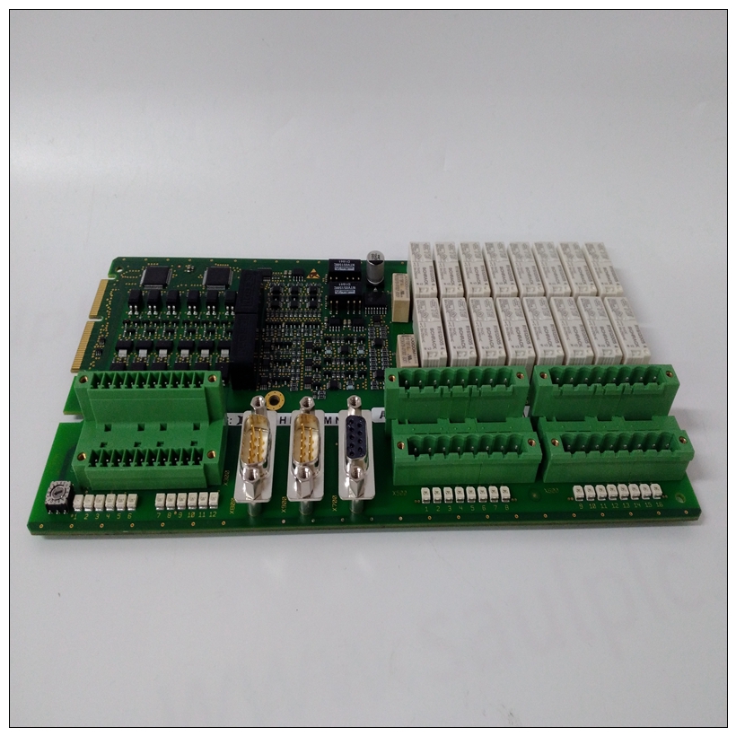
UCD208A101 3BHE020018R0101處理器卡件,ABB產品重量
ISF控制位允許其他VMEbus主機引起VMEchip釋放其對VMEbus SYSFAIL的貢獻*線這是為了讓軟件能夠確定電路板出現故障。應該注意的是,ISF位沒有對BRDFAIL狀態位的影響。將位設置為1將禁止VMEchip無法激活VMEbus SYSFAIL*行。這一位是由SYSRESET清除。SCON狀態位反映了收割臺J3。連接J3針腳1和2時,啟用MVME147作為系統控制器,SCON位為1。


UCD208A101 3BHE020018R0101處理器卡件否則它為0。位7 R&H位允許其他VMEbus主機重置MVME147。MVME147保持重置狀態的時間與設置R&H位時。該位由SYSRESET清除。1.GCSR基址配置寄存器必須編程以允許GCSR寄存器集為了響應VMEbus訪問,此函數將啟用。2.如果MVME147設置了自己的R&H,則會導致其自身保持重置狀態,直到其他主機將位清除為0。3.軟件不得在短時間內激活R&H35微秒。4、當本地MPU正在執行VMEbus循環。MC68030可以讀取和寫入該寄存器。VMEbus只能讀取它。該寄存器允許唯一識別電路板的軟件。整體寄存器由SYSRESETIntroduction清除本章提供了MVME147的功能描述。功能描述概述了模塊,然后詳細描述了模塊的每個部分。MVME147的框圖如圖5-1所示
The ISF control bit allows other VMEbus masters to cause the
VMEchip to release its contribution to the VMEbus SYSFAIL*
line. This is provided so that software can determine how many
boards have failed. It should be noted that the ISF bit has no
effect on the BRDFAIL status bit. Setting the bit to 1 inhibits the
VMEchip from activating the VMEbus SYSFAIL* line. This bit is
cleared by SYSRESET. The SCON status bit is a reflection of the configuration of
header J3. When J3 pins 1 and 2 are connected, enabling the
MVME147 as system controller, the SCON bit is 1. Otherwise it
is 0.
Bit 7 The R&H bit allows other VMEbus masters to reset the
MVME147. The MVME147 is held in the reset state for as long
as the R&H bit is set. This bit is cleared by SYSRESET. 1. The GCSR Base Address Configuration Register
must be programmed to allow the GCSR set of registers
to respond to VMEbus accesses for this function to be
enabled.
2. If the MVME147 sets its own R&H, it causes itself to
be maintained in a reset state until some other master
clears the bit to 0.
3. Software must never activate R&H for shorter than
35 microseconds.
4. The R&H bit should not be set while the local MPU
is executing a VMEbus cycle.The MC68030 can both read and write to this register.
The VMEbus can only read it. This register allows the
software to uniquely identify boards. The whole
register is cleared by SYSRESETIntroduction
This chapter provides a functional description of the MVME147.
The functional description provides an overview of the module,
followed by a detailed description of each section of the module.
The block diagram of the MVME147 is shown in Figure 5-1


