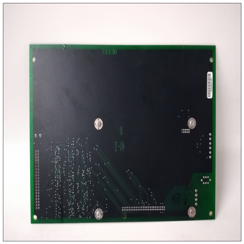
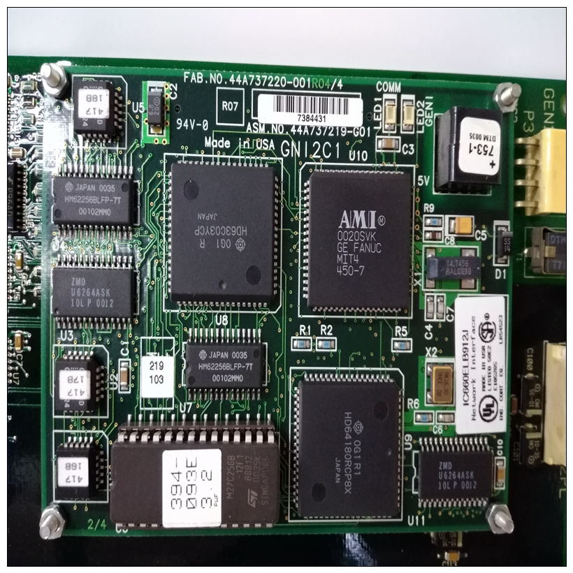
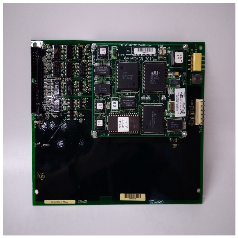
DS200ADGIH1AAA燃機模塊,GE怎么使用
系統控制器選擇標題(J3)標題J3允許您選擇MVME147作為系統控制器。拆下跨接導線后,該模塊不用作系統控制器。模塊出廠時已安裝跳線(系統控制器)。串行端口4時鐘配置選擇標頭(J8、J9)串行端口4可以配置為使用TRXC4和RTXC4信號線。


DS200ADGIH1AAA燃機模塊MVME147上的標題J8和J9模塊配置部分時鐘信號。剩下的時鐘線的配置是使用上的報頭J15完成的MVME712M模塊。參考MVME712M過渡收割臺J15的模塊和P2適配器板用戶手冊配置模塊在出廠時帶有插腳2上的跳線J8的3(接收RTXC4)和J9的引腳1和2(驅動TRXC4)。安裝說明配置MVME147的標頭并安裝如前所述,將選定的ROM安裝在插槽中系統中的MVME147模塊如下:1、關閉所有設備電源并斷開電源來自交流電源的電纜。在通電時連接模塊可能會導致損壞模塊上的部件。可能導致死亡的危險電壓包括:存在于該設備中。在以下情況下,請格外小心:處理、測試和調整。2、按照設備說明卸下機箱蓋用戶手冊。3.從以下位置的相應卡槽中卸下填充板:機箱的前部和后部(如果機箱有后部卡保持架)。如果MVME147配置為系統控制器,將其安裝在最左側的卡插槽(插槽1)中,以啟動總線正確授予菊花鏈。將安裝MVME147在底盤前部;MVME712過渡模塊可以安裝在機箱的前部或后部。注:每個MVME147都分配了一個以太網站住址地址是08003E2xxxxx,其中xxxxx是分配給模塊的唯一編號;i、 e.每MVME147對于xxxxx具有不同的值。每個以太網站地址都顯示在標簽上至MVME147的背板連接器P2。在里面附加
System Controller Select Header (J3)
Header J3 allows you to select the MVME147 as system controller.
With the jumper removed, the module is not used as system
controller. The module is shipped with the jumper installed
(system controller). Serial Port 4 Clock Configuration Select Headers (J8, J9)
Serial port 4 can be configured to use clock signals provided by the
TRXC4 and RTXC4 signal lines. Headers J8 and J9 on the MVME147
module configure part of the clock signals. The remaining
configuration of the clock lines is accomplished using header J15 on
the MVME712M module. Refer to the MVME712M Transition
Module and P2 Adapter Board User's Manual for header J15
configuration. The module is shipped with the jumper on pins 2
and 3 of J8 (receiving RTXC4), and on pins 1 and 2 of J9 (driving
TRXC4).Installation Instructions
When you have configured the MVME147’s headers and installed
the selected ROMs in the sockets as described previously, install the
MVME147 module in the system as follows:
1. Turn all equipment power OFF and disconnect the power
cable from the AC power source. Connecting modules while power is applied may result
in damage to components on the module.Dangerous voltages, capable of causing death, are
present in this equipment. Use extreme caution when
handling, testing, and adjusting.
2. Remove the chassis cover as instructed in the equipment
user's manual.
3. Remove the filler panel(s) from the appropriate card slot(s) at
the front and rear of the chassis (if the chassis has a rear card
cage). If the MVME147 is configured as the system controller,
install it in the left-most card slot (slot 1) to initiate the bus
grant daisy-chain correctly. The MVME147 is to be installed
in the front of the chassis; the MVME712 transition module
may be installed in the front or rear of the chassis.
Note Every MVME147 is assigned an Ethernet station
address. The address is $08003E2xxxxx where xxxxx is
the unique number assigned to the module; i.e., every
MVME147 has a different value for xxxxx.
Each Ethernet station address is displayed on a label
attached to the MVME147’s backplane connector, P2. In
addition


