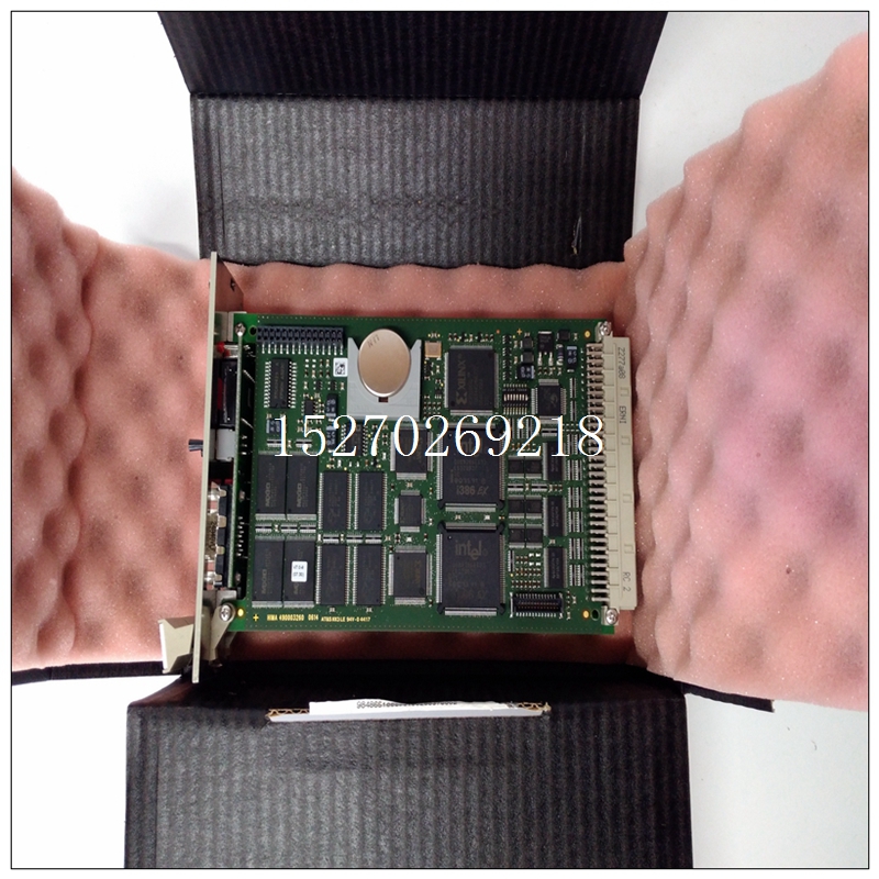
HIMA F2101輸出卡件
3 PACSystems*RX3i系統手冊第12節GFK-2314T 2019年9月模擬輸出模塊450 10.3.11 LED:ALG704和ALG708模塊OK LED指示模塊狀態。現場狀態LED指示外部+24V直流電源是否存在且高于最低水平,以及是否存在故障。所有LED均由背板電源總線供電。LED指示模塊正常開啟綠色:模塊正常且已配置。快速閃爍綠色:模塊正在執行通電順序。綠色或琥珀色緩慢閃爍:模塊正常,但未配置。關閉:模塊故障或無背板電源現場狀態為綠色,任何已啟用通道上無故障,存在接線板,且現場電源存在。ON琥珀色和TB綠色:接線板已安裝,至少一個通道出現故障,或現場電源不存在。ON琥珀色和TB紅色:接線板未完全移除,仍檢測到現場電源。OFF和TB紅色:接線板不存在,未檢測到現場電源。TB ON紅色:接線板不存在或未完全就位。請參閱上文。ON綠色:存在接線板。請參閱上文。OFF:模塊沒有背板電源。10.3.12規格:ALG704和ALG708輸出范圍電流:0至20mA,4至20mA電壓:±10 Vdc,0至10 Vdc背板電源要求ALG704/708-CB或更早版本:3.3V ALG704/08-DC或更高版本時最大375 mA:模塊內功耗為3.3V時最大250 mA(Vuser=24V)IC695ALG704:最大4.8瓦IC695ALG008:最大7.25瓦PACSystems*RX3i系統手冊第12節GFK-2314T 2019年9月模擬輸出模塊451熱降級IC695ALD704:無IC695ALF708:電壓模式:無電流模式:參見圖305。外部電源Vuser電壓范圍:+19.2V至+30 Vdc ALG704所需電流:150 mA ALG708所需最大電流:250 mA最大分辨率±10 Vdc:15.9位,0至10 Vdc:14.9位,4至20mA:15.6位輸出數據格式可配置為浮點IEEE 32位或32位字段中的16位整數更新速率8 ms(近似值,所有8個通道)(取決于I/O掃描時間,取決于應用程序)。輸出過電壓保護電流輸出僅:-30 V,持續60秒,+30V一小時校準精度64在25°C時精確到滿量程的0.15%以內在60°C時準確到滿量程0.30%以內輸出負載電抗電流:最大10μH,電壓:1μF最大輸出負載電流:Vuser=20V時最大850W電壓:2kW最小輸出增益漂移電壓輸出:每攝氏度20ppm典型電流輸出:每華氏度35ppm典型輸出設定時間電壓或電流輸出:2ms,0至95%。隔離,場至背板2550 Vdc,1秒最大符合性電壓Vuser
3 PACSystems* RX3i System Manual Section 12 GFK-2314T Sept. 2019 Analog Output Modules 450 10.3.11 LEDs: ALG704 and ALG708 The Module OK LED indicates module status. The Field Status LED indicates whether the external +24Vdc power supply is present and is above the minimum level and whether or not faults are present. All LEDs are powered from the backplane power bus. LED Indicates Module OK ON Green: Module OK and configured. Quick Flashing Green: Module performing power-up sequence. Slow Flashing Green or Amber: Module OK but not configured. OFF: Module is defective or no backplane power present Field Status ON Green No faults on any enabled channel, Terminal Block is present, and field power is present. ON Amber and TB Green: Terminal Block is installed, fault on at least one channel, or field power is not present. ON Amber and TB Red: Terminal Block not fully removed, field power still detected. OFF and TB Red: Terminal block not present and no field power is detected. TB ON Red: Terminal block not present or not fully seated. Refer to above. ON Green: Terminal block is present. Refer to above. OFF: No backplane power to module. 10.3.12 Specifications: ALG704 and ALG708 Output Ranges Current: 0 to 20mA, 4 to 20mA Voltage: ± 10 Vdc, 0 to 10 Vdc Backplane Power Requirements ALG704/708-CB or earlier: 375 mA maximum at 3.3V ALG704/708-DC or later: 250 mA maximum at 3.3V Power Dissipation within Module (Vuser=24V) IC695ALG704: 4.8 Watts maximum IC695ALG708: 7.25Watts maximum PACSystems* RX3i System Manual Section 12 GFK-2314T Sept. 2019 Analog Output Modules 451 Thermal De-rating IC695ALG704: None IC695ALG708: Voltage mode: none Current mode: Refer to Figure 305. External Power Supply Vuser Voltage Range: +19.2V to +30 Vdc Current required for ALG704: 150mA maximum Current required for ALG708: 250mA maximum Resolution ±10 Vdc: 15.9 bits, 0 to 10 Vdc: 14.9 bits, 0 to 20mA: 15.9 bits, 4 to 20mA: 15.6 bits Output Data Format Configurable as floating-point IEEE 32-bit or 16-bit integer in a 32-bit field Update Rate 8 ms (approximate, all eight channels) (Determined by I/O scan time, application dependent.) Output Over-voltage Protection Current outputs only: -30V for 60 seconds, +30V for one hour Calibrated Accuracy64 Accurate to within 0.15% of full scale at 25°C Accurate to within 0.30% of full scale at 60°C Output Load Reactance Current: 10μH maximum, Voltage: 1μF maximum Maximum Output Load Current: 850W maximum at Vuser = 20V Voltage: 2kW minimum Output Gain Drift Voltage output: 20ppm per degree C typical Current output: 35ppm per degree C typical Output Settling Time Voltage or current output: 2ms, 0 to 95%. Isolation, Field to Backplane 2550 Vdc for one second Maximum Compliance Voltage Vuser


