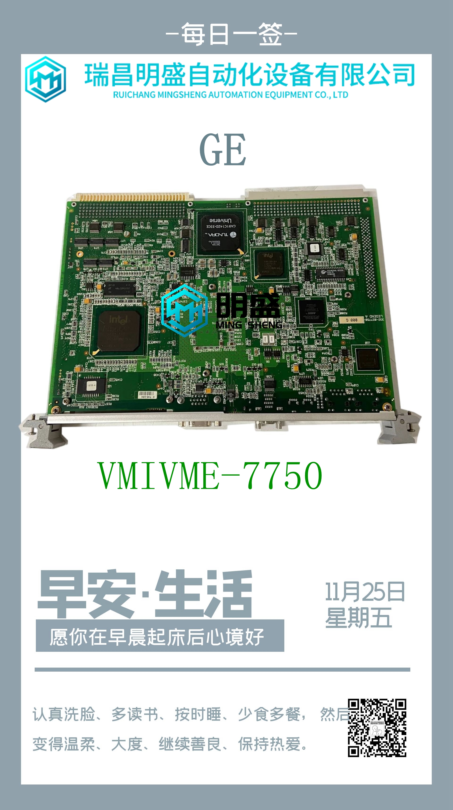
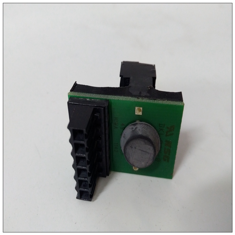
HIMA F3105自動化卡件
I如果該模塊位于擴展或遠程背板中,其主要電源可以是來自背板電源的隔離+24V直流電源,也可以是連接到該模塊接線板的外部隔離+24V dc電源。如果外部電源設置在27.5-30 Vdc之間,它將從隔離24Vdc系統電源接管負載。請注意,如果希望在背板斷電期間保持保持最后狀態操作,則應使用外部電源。10.1.2 LED當模塊電源運行時,模塊OK LED亮起。10.1.3規格:ALG390電壓范圍-10至+10伏PACSystems*RX3i系統手冊第12節GFK-2314T 2019年9月模擬輸出模塊431校準工廠校準至2.5毫伏/計數電源電壓(標稱)+24V dc,來自背板或用戶提供的電壓源上的隔離+24V dc,對于輸出:10.1.4.1 D/A位與輸出電壓60在存在嚴重RF干擾(IEC 801–3,10V/m)的情況下,精度可能會降低到±50 mV。PACSystems*RX3i系統手冊第12節GFK-2314T 2019年9月模擬輸出模塊432 D/A BITS(十進制)電壓(V)10 0 10 4000 4000 0圖291:D/A位與輸出電壓10.1.4.2縮放:ALG390輸出縮放顯示在下圖中。單位(十進制)電壓(V)10 0 10 32000 32000 0圖292:縮放單位與輸出電壓10.1.5現場接線:ALG390端子連接1無連接2無連接3輸出1 PACSystems*RX3i系統手冊第12節GFK-2314T 2019年9月模擬輸出模塊433 4輸出2 5輸出1公共6輸出2公共7輸出屏蔽端接點1 8屏蔽端接點輸出2 9無連接10無連接11-13輸出默認選擇跳線12無連接14無連接15無連接16無連接17外部+24Vdc電源+18無連接19外部+24Vdc電源-20無連接為了最大限度地減少電容負載和噪聲,所有現場連接都應使用良好等級的絞合屏蔽儀表電纜進行接線。屏蔽應連接到用戶終端連接器塊上的GND。GND連接提供了對背板(機架接地)的訪問,從而對任何屏蔽漏極電流引起的噪聲產生了卓越的抑制。DEF0是可選的輸出默認跳線。當CPU處于停止或重置模式時,它決定兩個輸出的操作。如果輸出默認為0,則應安裝跳線。如果輸出應保持其最后狀態(從CPU接收的最后有效命令值),則不應安裝跳線。如圖所示,可安裝可選的外部+24V直流電源。PACSystems*RX3i系統手冊第12節GFK-2314T 2019年9月模擬輸出模塊434 10.2模擬輸出模塊電流2通道:IC694ALG391模塊0K IC694ALGA391 Q1 Q2圖293:IC694A LG391 2通道模擬電流輸出模塊IC694ALG391有兩個輸出通道,每個通道能夠將12位二進制(數字)數據轉換為現場設備的模擬輸出信號。可以使用模塊上的跳線設置每個輸出,以產生兩個范圍之一的輸出信號:? 0至20毫安? 4至20 mA。每個輸出也可以設置為精度較低的電壓源。通過模塊端子上的跳線或電阻器選擇電流或電壓輸出。每次掃描時都會更新兩個通道。如果CPU進入停止模式或重置,則該模塊上的輸出可設置為默認值0/4 mA或保持–最后狀態。通過該模塊端子板上的跳線選擇輸出默認狀態。
f this module is located in an Expansion or Remote backplane, its primary power source can be either the Isolated +24Vdc from the backplane power supply or an external Isolated +24Vdc power supply connected to the terminal block of this module. If the external source is set between 27.5-30 Vdc, it takes over the load from the Isolated 24Vdc system supply. Note that an external source should be used if it is desired to maintain hold last state operation during a loss of backplane power. 10.1.2 LED The Module OK LED is ON when the module power supply is operating. 10.1.3 Specifications: ALG390 Voltage Range -10 to +10 volts PACSystems* RX3i System Manual Section 12 GFK-2314T Sept. 2019 Analog Output Modules 431 Calibration Factory calibrated to 2.5 mV per count Supply Voltage (nominal) +24Vdc, from isolated +24Vdc on backplane or user-supplied voltage source, for the output: 10.1.4.1 D/A Bits versus Output Voltage 60 In the presence of severe RF interference (IEC 801–3, 10V/m), accuracy may be degraded to ±50 mV. PACSystems* RX3i System Manual Section 12 GFK-2314T Sept. 2019 Analog Output Modules 432 D/A BITS (decimal) VOLTAGE (V) 10 0 10 4000 4000 0 Figure 291: D/A Bits versus Output Voltage 10.1.4.2 Scaling: ALG390 Scaling of the output is displayed in the following figure. Units (decimal) VOLTAGE (V) 10 0 10 32000 32000 0 Figure 292: Scaling Units versus Output Voltage 10.1.5 Field Wiring: ALG390 Terminal Connection 1 No connection 2 No connection 3 Output 1 PACSystems* RX3i System Manual Section 12 GFK-2314T Sept. 2019 Analog Output Modules 433 4 Output 2 5 Output 1 Common 6 Output 2 Common 7 Shield termination point for output 1 8 Shield termination point for output 2 9 No connection 10 No connection 11 - 13 Output default selection jumper 12 No connection 14 No connection 15 No connection 16 No connection 17 External +24Vdc Power Supply + 18 No connection 19 External +24Vdc Power Supply - 20 No connection To minimize capacitive loading and noise, all field connections should be wired using a good grade of twisted, shielded instrumentation cable. The shields should be connected to GND on the user terminal connector block. The GND connection provides access to the backplane (frame ground) resulting in superior rejection of noise caused by any shield drain currents. DEF0 is the optional Output Default Jumper. It determines the operation of both outputs when the CPU is in Stop or Reset mode. The jumper should be installed if outputs should default to 0. The jumper should not be installed if outputs should hold their last state (the last valid commanded value received from the CPU). An optional external +24Vdc supply can be installed as shown. PACSystems* RX3i System Manual Section 12 GFK-2314T Sept. 2019 Analog Output Modules 434 10.2 Analog Output Module Current 2-Channel: IC694ALG391 MODULE 0K IC694ALG391 Q1 Q2 Figure 293: IC694ALG391 The 2–Channel Analog Current Output module, IC694ALG391, has two output channels, each capable of converting 12 bits of binary (digital) data to an analog output signal for field devices. Each output can be set using a jumper on the module to produce output signals in one of two ranges: ? 0 to 20 mA ? 4 to 20 mA. Each output may also be set up as a less accurate voltage source. The selection of current or voltage output is made with a jumper or resistor on the module terminals. Both channels are updated on every scan. The outputs on this module can be set up to either Default to 0/4 mA or Hold– Last–State if the CPU goes to the Stop mode or Reset. Selection of the output default state is made by a jumper on the terminal board of this module.


