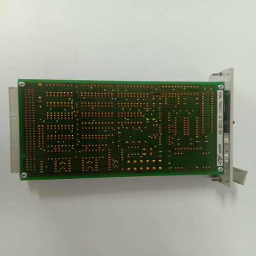
HIMA F3316機器人卡件,控制卡件
在這種類型的系統中,一半的多用途電源必須連接到一個電源,另一半必須連接到單獨的電源。這種布置提供了如上所述的基本冗余系統的所有優點以及電源冗余。只要最小數量的單元保持通電,前面板開關可用于移除單個電源。PACSystems*RX3i系統手冊第5節GFK-2314T 2019年9月電源97多用途電源多用途電源開關設備圖82:電源冗余連接4.3浮動中性點(IT)系統的交流電源連接如果交流輸入電源安裝在中性線未參考保護接地的系統中,必須遵循特殊安裝說明,以防止電源損壞。浮動中性點系統是一種配電布線系統,其中中性點和保護接地不通過可忽略的阻抗連接在一起。在歐洲,這被稱為IT系統(參考IEC950)。在浮動中性點系統中,從輸入端子到保護接地測量的電壓可能超過264Vac最大輸入電壓電源規格。L1 N PE圖83:浮動中性線4.3.1浮動中性線系統的特殊說明輸入電源端子應根據第2.6.6.1節“電源現場接線”中的說明進行接線,以下情況除外。1) 對于IC695電源,端子5或6與端子7之間不得安裝跳線。2) 對于IC694和IC693電源,電源模塊的端子3和4之間不得安裝跳線。3) 必須安裝電壓浪涌保護裝置,如MOV:? 從L1到接地? 從L2(中性點)到接地電壓浪涌裝置的額定值必須確保系統免受超過線路電壓+100V+(N-PE)MAX的電力線瞬變的影響。N-PE表示中性點和保護接地(PE)之間的電壓電勢。例如在中性點浮置在地上50 Vac的240伏AC系統中,瞬態保護的額定值應為:PACSystems*RX3i系統手冊第5節GFK-2314T 2019年9月電源98 240 Vac+100 Vac+50 Vac=390 Vac 4.3.2非浮動中性點系統系統,其中配電線路的一條腿連接到保護接地,或配電線路的兩條腿之間的抽頭連接到保護性接地系統。非浮動中性系統不需要特殊的安裝程序。圖84:非浮動中性線L1 N PE L N/PE L1 PE L2 PACSystems*RX3i系統手冊第5節GFK-2314T 2019年9月電源99 4.4電源,120/240 Vac或125Vdc,40 W:IC695PSA040電源IC695PS040是一個40瓦電源,從85至264Vac或100 Vdc至300 Vdc的輸入電壓源工作。該電源提供三個輸出:? +5.1Vdc輸出,? +24Vdc繼電器輸出,可用于為輸出繼電器模塊上的電路供電。? +3.3Vdc。此輸出由具有IC695目錄號的RX3i模塊內部使用。警告:PACSystems RX3i(IC695產品目錄號)通用背板中只能使用一個IC695PSA040。此電源不能與冗余或增加容量模式下的其他RX3i電源一起使用。如果不小心將IC695PSA040C或更早版本的電源安裝在與另一個RX3i電源相同的背板中,可能會導致設備損壞。如果所需的模塊數量超過電源的容量,
In this type of system, half of the Multi-purpose power supplies must be connected to one power source and the other half must be connected to a separate source. This arrangement provides all the advantage of a Basic Redundancy system, as described above, plus power source redundancy. The front panel switch may be used to remove an individual power supply as long as the minimum number of units remains powered up. PACSystems* RX3i System Manual Section 5 GFK-2314T Sept. 2019 Power Supplies 97 Multipurpose Power Supply Multipurpose Power Supply Multipurpose Power Supply Multipurpose Power Supply Power Source A Power Source B External Switching Device Two Extra Load-Sharing Power Supplies Provide Power Source Redundancy Example: Two Load-Sharing Power Supplies Needed to Meet Load Requreements External Switching Device Figure 82: Connections for Power Source Redundancy 4.3 AC Power Supply Connections for Floating Neutral (IT) Systems If an AC input power supply is installed in a system where the Neutral line is not referenced to Protective Earth Ground, special installation instructions must be followed to prevent damage to the power supply. A Floating Neutral System is a system of power distribution wiring where Neutral and Protective Earth Ground are not tied together by negligible impedance. In Europe, this is referred to as an IT system (refer to IEC950). In a Floating Neutral System, voltages measured from input terminals to protective earth ground may exceed the 264Vac maximum input voltage power supply specification. L1 N PE Figure 83: Floating Neutral 4.3.1 Special Instructions for Floating Neutral Systems The input power terminals should be wired according to the instructions in Power Supply Field Wiring, Section 2.6.6.1 with the following exceptions. 1) For IC695 power supplies, no jumper may be installed between terminal 5 or 6 and terminal 7. 2) For IC694 and IC693 power supplies, no jumper may be installed between terminals 3 and 4 of the power supply module. 3) Voltage surge protection devices such as MOVs must be installed: ? From L1 to earth ground ? From L2 (Neutral) to earth ground The voltage surge devices must be rated such that the system is protected from power line transients that exceed Line voltage + 100V + (N-PE)MAX. The expression N-PE refers to the voltage potential between neutral and Protective Earth (PE) ground. For example, in a 240 Volt AC system with neutral floating 50 Vac above earth ground, the transient protection should be rated at: PACSystems* RX3i System Manual Section 5 GFK-2314T Sept. 2019 Power Supplies 98 240 Vac + 100 Vac + 50 Vac = 390 Vac 4.3.2 Non-Floating Neutral System Systems where one leg of the power distribution wiring is tied to Protective Earth or a tap between two legs of the power distribution wiring is tied to Protective Earth are not Floating Neutral Systems. Non-floating neutral systems do not require special installation procedures. Figure 84: Non-Floating Neutral Wiring L1 N PE L N/PE L1 PE L2 PACSystems* RX3i System Manual Section 5 GFK-2314T Sept. 2019 Power Supplies 99 4.4 Power Supply, 120/240 Vac or 125Vdc, 40 W: IC695PSA040 Power Supply IC695PSA040 is a 40-Watt supply that operates from an input voltage source in the range of 85 to 264Vac or 100 Vdc to 300 Vdc. This power supply provides three outputs: ? +5.1Vdc output, ? +24Vdc relay output that can be used to power circuits on Output Relay modules. ? +3.3Vdc. This output is used internally by RX3i modules with IC695 catalog numbers. CAUTION Only one IC695PSA040 can be used in a PACSystems RX3i (IC695 catalog number) Universal Backplane. This power supply cannot be used with other RX3i power supplies in redundant or increased capacity modes. Power supply version IC695PSA040C or earlier may cause equipment damage if inadvertently installed in the same backplane as another RX3i power supply. If the number of modules required exceeds the capacity of the power supply,


