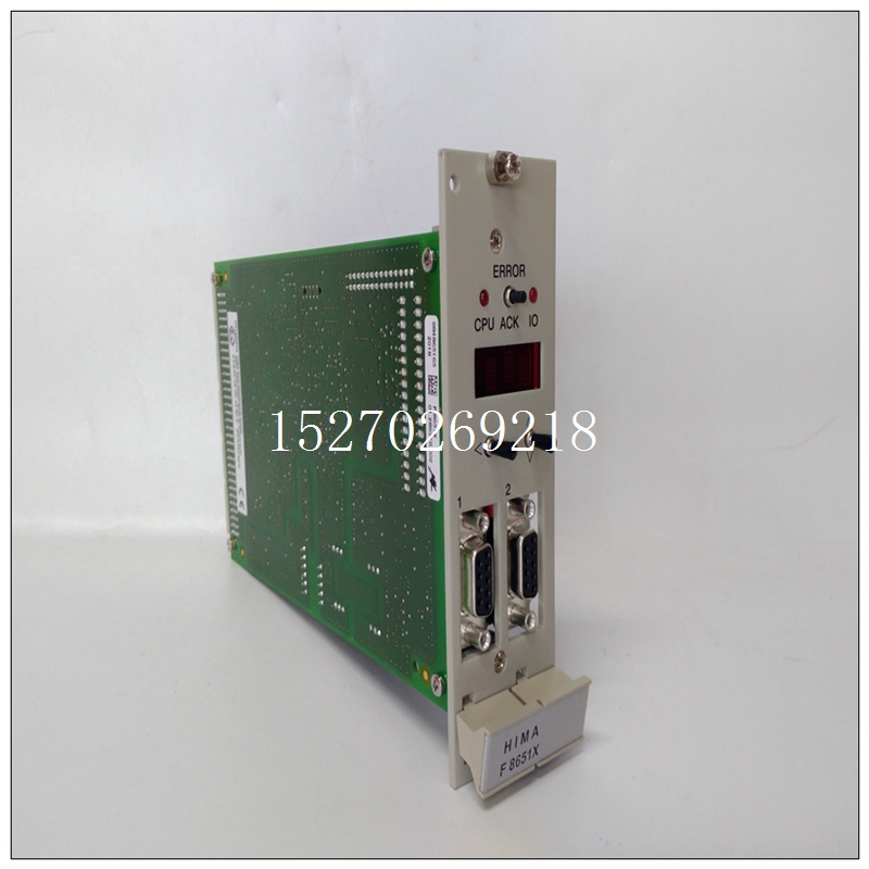
HIMA F3406a備件模塊
是否圖49:電源輸入端子的正確接線規程? 對于IC694電源,每個端子接受一根AWG#14(2.1mm2)或兩根AWG#16(1.3mm2)75°C(167°F)銅線。電源端子的建議扭矩為1.36 Nm(12 in-lb)。每個端子都可以接受實心或絞合導線。同一端子中的多條電線應具有相同的類型(實心或絞合)和尺寸。圖50:I/O模塊+/L1-/N/L2跳線接地的IC695電源端子24VDC輸出圖51:IC694電源端子§僅用于擴展(IC694)電源,底部端子可訪問擴展背板的隔離+24V DC輸出,該輸出可用于為某些IC694模塊的輸入電路供電。有關信息,請參閱第4.2節模塊負載要求表。PACSystems*RX3i系統手冊第3節GFK-2314T 2019年9月安裝66注意事項如果隔離24Vdc電源過載或短路,PLC將停止運行。PACSystems*RX3i系統手冊第3節GFK-2314T 2019年9月安裝67 2.6.6.2交流電源連接將火線和中性線或L1和L2連接到適當的電源端子。2.6.6.3直流電源連接所有RX3i電源都具有直流輸入功能。將直流電源的+和-導線連接到適當的端子。這些連接是極性敏感的直流電源。2.6.6.3.1接地連接將安全接地線連接到標有接地符號的端子。2.6.6.4外部過電壓保護電源模塊上的接地和MOV端子通常通過用戶安裝的跳線連接到機架接地(如圖52所示)。如果不需要過電壓保護或在上游提供過電壓保護,則不需要跳線。在具有浮動中性輸入的系統中(中性線未參考保護接地),不得安裝此跳線。此外,在浮動中性點系統中,電壓浪涌保護裝置(如MOV)必須從L1安裝到接地,從L2(中性點)安裝到接地線。+/L1-/N/L2跳線帶將過電壓保護裝置連接至機架接地機架接地螺釘端子圖52:外部過電壓保護2.6.6.5浮動中性點(IT)系統的交流電源連接如果在中性線未參考保護接地的系統中安裝交流輸入電源,必須遵循特殊的安裝說明,以防止損壞電源。浮動中性點系統是一種配電布線系統,其中中性點和保護接地不通過可忽略的阻抗連接在一起。在歐洲,這被稱為IT系統(參考IEC950)。在浮動中性點系統中,從輸入端子到保護接地測量的電壓可能超過264Vac最大輸入電壓電源規格。L1 N PE圖53:浮動中性點PACSystems*RX3i系統手冊第3節GFK-2314T 2019年9月安裝68 2.6.6.6非浮動中性點系統系統的交流電源連接,其中配電線路的一條腿連接到保護接地,或配電線路的兩條腿之間的抽頭連接到保護地。非浮動中性系統。非浮動中性系統不需要特殊的安裝程序。圖54:中性點不浮動(接地)2.6.6.7浮動中性點系統說明1。輸入電源端子的接線應如上圖49至圖51所示。2.不得在電源模塊的端子3和4之間安裝跳線。3.必須安裝電壓浪涌保護裝置,如MOV:? 從L1到接地? 從L2(中性點)到接地電壓浪涌裝置的額定值必須確保系統免受超過線路電壓+100 Vac+(N-PE)MAX的電力線瞬變的影響。N-PE表示中性點和保護接地(PE)之間的電壓電勢。例如,在中性點浮動的240伏交流系統中
Yes No Figure 49: Correct Wiring Practice for Power Supply Input Terminals ? For IC694 Power Supplies, each terminal accepts one AWG #14 (2.1mm2 ) or two AWG #16 (1.3mm2 ) copper 75°C (167°F) wires. The suggested torque for the Power Supply terminals is 1.36 Nm (12 in-lb). Each terminal can accept solid or stranded wires. Multiple wires in the same terminal should be of the same type (solid or stranded) and size. Figure 50: IC695 Power Supply Terminals 24VDC Output for I/O Modules + / L1 - / N / L2 Jumper Ground Figure 51: IC694 Power Supply Terminals § For Expansion (IC694) Power Supplies only, the bottom terminals provide access to the Isolated +24Vdc output of the Expansion Backplane, which can be used to power input circuits for certain IC694 modules. Refer to the table Module Load Requirements, Section 4.2 for information. PACSystems* RX3i System Manual Section 3 GFK-2314T Sept. 2019 Installation 66 CAUTION If the Isolated 24Vdc supply is overloaded or shorted, the PLC will stop operation. PACSystems* RX3i System Manual Section 3 GFK-2314T Sept. 2019 Installation 67 2.6.6.2 AC Power Source Connections Connect the hot and neutral wires or lines L1 and L2 to the appropriate Power Supply terminals. 2.6.6.3 DC Power Source Connections All RX3i Power Supplies have DC input capabilities. Connect the + and - wires from the DC source to the appropriate terminals. These connections are polarity-sensitive DC-only supplies. 2.6.6.3.1 Ground Connection Connect the safety ground wire to the terminal marked with a ground symbol. 2.6.6.4 External Overvoltage Protection The Ground and MOV terminals on a Power Supply module are normally connected to frame ground with a user-installed jumper (as shown in Figure 52). If overvoltage protection is not required or is supplied upstream, no jumper is needed. In systems with a floating neutral input (the neutral line is not referenced to Protective Earth Ground), this jumper must NOT be installed. In addition, in a floating neutral system, voltage surge protection devices such as MOVs must be installed from L1 to earth ground, and from L2 (Neutral) to earth ground. + / L1 - / N / L2 Jumper strap connects overvoltage protection devices to frame ground Frame Ground Screw Terminals Figure 52: External Overvoltage Protection 2.6.6.5 AC Power Supply Connections for Floating Neutral (IT) Systems If an AC input power supply is installed in a system where the Neutral line is not referenced to Protective Earth Ground, special installation instructions must be followed to prevent damage to the power supply. A Floating Neutral System is a system of power distribution wiring where Neutral and Protective Earth Ground are not tied together by negligible impedance. In Europe, this is referred to as an IT system (refer to IEC950). In a Floating Neutral System, voltages measured from input terminals to protective earth ground may exceed the 264Vac maximum input voltage power supply specification. L1 N PE Figure 53: Floating Neutral PACSystems* RX3i System Manual Section 3 GFK-2314T Sept. 2019 Installation 68 2.6.6.6 AC Power Supply Connections for Non-Floating Neutral System Systems where one leg of the power distribution wiring is tied to Protective Earth or a tap between two legs of the power distribution wiring is tied to Protective Earth are not Floating Neutral Systems. Non-floating neutral systems do not require special installation procedures. Figure 54: Neutral Not Floating (Tied to Ground) 2.6.6.7 Instructions for Floating Neutral Systems 1. The input power terminals should be wired as shown in Figure 49 through Figure 51 above. 2. No jumper may be installed jumper between terminals 3 and 4 of the Power Supply module. 3. Voltage surge protection devices such as MOVs must be installed: ? From L1 to earth ground ? From L2 (Neutral) to earth ground The voltage surge devices must be rated such that the system is protected from power line transients that exceed Line voltage + 100 Vac + (N-PE)MAX. The expression N-PE refers to the voltage potential between neutral and Protective Earth (PE) ground. For example, in a 240 Volt AC system with neutral floating


