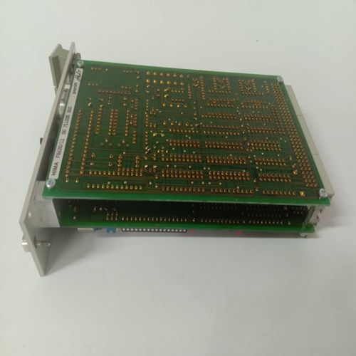
HIMA F4101模擬量輸入模塊
圖29:20連接器可拆卸接線板,帶系帶著陸位置,注明PACSystems*RX3i系統(tǒng)手冊第3節(jié)GFK-2314T 2019年9月安裝49 2.6.4.7安裝或拆卸20連接器接線板組件(有關(guān)安裝或拆卸36針接線板組件的說明,請參閱第17章)。比較端子組件門上的標(biāo)簽上的模塊目錄號和側(cè)面的標(biāo)簽,以確保它們匹配。如果接線端子板安裝在錯誤的模塊類型上,則系統(tǒng)通電時模塊可能會損壞。警告:安裝或拆卸接線板組件時,必須關(guān)閉現(xiàn)場電源。2.6.4.7.1安裝接線端子(圖30):1。將接線板組件底部的樞軸鉤插入模塊底部的插槽中。2.向上轉(zhuǎn)動接線盒組件,以接合連接器。3.朝模塊方向按壓接線板組件,直到釋放桿閂鎖卡入到位。檢查以確保接線板牢固就位。1 2 3圖30:將接線板安裝到I/O模塊PACSystems*RX3i系統(tǒng)手冊第3節(jié)GFK-2314T 2019年9月安裝50釋放桿圖31:從I/O模塊上卸下前釋放桿的使用2.6.4.7.2卸下接線板:1。打開接線盒門。2.向上推釋放桿(圖31)以解鎖接線板。3.將接線板從模塊上拉開,直到觸點分離且底部樞軸鉤脫離。PACSystems*RX3i系統(tǒng)手冊第3節(jié)GFK-2314T 2019年9月安裝51 2.6.4.8安裝或拆除接線板蓋可以拆除接線板組件蓋,以便更容易接近端子。警告:即使背板電源已關(guān)閉,模塊的螺絲端子上可能存在來自用戶設(shè)備的潛在危險電壓。處理模塊的可拆卸接線板組件及其連接的任何電線時,請務(wù)必小心。REL EASE LEV ER圖32:將接線板拔出或插入其蓋子2.6.4.8.1從蓋子上拆下接線板:1。抓住接線板蓋的側(cè)面。2.如圖32所示,下拉接線板底部。2.6.4.8.2將接線板插入其蓋中:要將接線板重新插入其蓋:1。將接線板的頂部與蓋子的底部對齊,確保接線板上的槽口與蓋子上的凹槽對齊。2.向上滑動接線板(圖32),直到其卡入到位。PACSystems*RX3i系統(tǒng)手冊第3節(jié)GFK-2314T 2019年9月安裝52 2.6.4.9與離散模塊的正負邏輯連接PACSystems RX3i模塊的正邏輯和負邏輯的IEC定義在以下章節(jié)中描述。2.6.4.9.1正邏輯正邏輯輸入模塊(圖33)將電流從輸入設(shè)備吸收到用戶公共或負電源總線。輸入裝置連接在正電源總線和輸入端子之間。正邏輯輸出模塊(圖34)從用戶公共或正電源總線向負載提供電流。負載連接在負電源總線和模塊輸出之間。0V IEC+24V SINK I N+圖33:正邏輯輸入電路0V+24V IEC SOURCE OUT+圖34:正邏輯輸出電路2.6.4.9.2負邏輯負邏輯輸入模塊(圖35)通過輸入設(shè)備向用戶公共或正電源總線提供電流。輸入設(shè)備連接在負電源總線和輸入端子之間。負邏輯輸出模塊(圖36)將電流從負載吸收到用戶公共或負電源總線。負載連接在正電源總線和輸出端子之間。PACSystems*RX3i系統(tǒng)手冊第3節(jié)GFK-2314T 2019年9月安裝53 0V+24V IEC SOURCE I N+圖35:負邏輯輸入電路+0V IEC+24V SINK OUT圖36:負邏輯輸出電路PACSystems*RX3i系統(tǒng)說明書第3節(jié)GFK-2314T2019年9月份安裝54 2.6.4.10模擬模塊扭曲接線,強烈建議將屏蔽儀表電纜用于模擬模塊輸入或輸出信號連接。屏蔽的正確接地也很重要。最大電氣噪音
Figure 29: 20 Connector detachable terminal block, landing position with tether, indicating PACSystems * RX3i system manual section 3 GFK-2314T installation in September 2019 49 2.6.4.7 Installation or removal of 20-connector terminal block assembly (see Chapter 17 for instructions on installation or removal of 36-pin terminal block assembly). Compare the module catalog number on the label on the terminal assembly door with the label on the side to ensure that they match. If the terminal block is installed on the wrong module type, the module may be damaged when the system is powered on. Warning: When installing or removing the terminal block assembly, the field power must be turned off. 2.6.4.7.1 Install wiring terminals (Figure 30): 1. Insert the pivot hook at the bottom of the terminal block assembly into the slot at the bottom of the module. 2. Turn the junction box assembly upwards to engage the connector. 3. Press the terminal block assembly toward the module until the release lever latch clicks into place. Check to ensure that the terminal block is firmly seated. 1 2 3 Figure 30: Installing the wiring board to the I/O module PACSystems * RX3i System Manual Section 3 GFK-2314T Installing the 50 release lever in September 2019 Figure 31: Removing the front release lever from the I/O module Use 2.6.4.7.2 Removing the wiring board: 1. Open the junction box door. 2. Push up the release lever (Figure 31) to unlock the terminal block. 3. Pull the terminal block away from the module until the contact is separated and the bottom pivot hook is disengaged. PACSystems * RX3i System Manual, Section 3, GFK-2314T, installed in September 2019, 51 2.6.4.8 Installing or removing the terminal block cover can remove the terminal block assembly cover to make it easier to access the terminals. Warning: Even if the backplane power is turned off, there may be potentially dangerous voltage from the user's equipment on the screw terminals of the module. Be careful when handling the removable terminal block assembly of the module and any wires connected to it. REL EASE LEV ER Figure 32: Pull out or insert the terminal block into its cover 2.6.4.8.1 Remove the terminal block from the cover: 1. Grasp the side of the terminal block cover. 2. As shown in Figure 32, pull down the bottom of the terminal block. 2.6.4.8.2 Insert the terminal block into its cover: insert the terminal block into its cover again: 1. Align the top of the terminal block with the bottom of the cover, and ensure that the notch on the terminal block is aligned with the groove on the cover. 2. Slide the terminal block up (Figure 32) until it clicks into place. PACSystems * RX3i System Manual, Section 3, GFK-2314T, installed in September 2019, 52 2.6.4.9 Positive and negative logic connection with discrete module. IEC definitions of positive logic and negative logic of PACSystems RX3i module are described in the following chapters. 2.6.4.9.1 Positive logic positive logic input module (Figure 33) absorbs current from input device to user common or negative power bus. The input device is connected between the positive power bus and the input terminal. The positive logic output module (Figure 34) provides current to the load from the user common or positive power bus. The load is connected between the negative power bus and the module output. 0V IEC+24V SINK I N+Figure 33: Positive logic input circuit 0V+24V IEC SOURCE OUT+Figure 34: Positive logic output circuit 2.6.4.9.2 Negative logic negative logic input module (Figure 35) provides current to user public or positive power bus through input device. The input device is connected between the negative power bus and the input terminal. The negative logic output module (Figure 36) absorbs the current from the load to the user common or negative power bus. The load is connected between the positive power bus and the output terminal. PACSystems * RX3i System Manual, Section 3, GFK-2314T, installed in September 2019, 53 0V+24V IEC SOURCE I N+Figure 35: Negative logic input circuit+0V IEC+24V SINK OUT Figure 36: Negative logic output circuit PACSystems * RX3i System Manual, Section 3, GFK-2314T, installed in September 2019, 54 2.6.4.10 analog module twisted wiring, it is strongly recommended to use shielded instrument cable for analog module input or output signal connection. Proper grounding of the shield is also important. Maximum electrical noise


