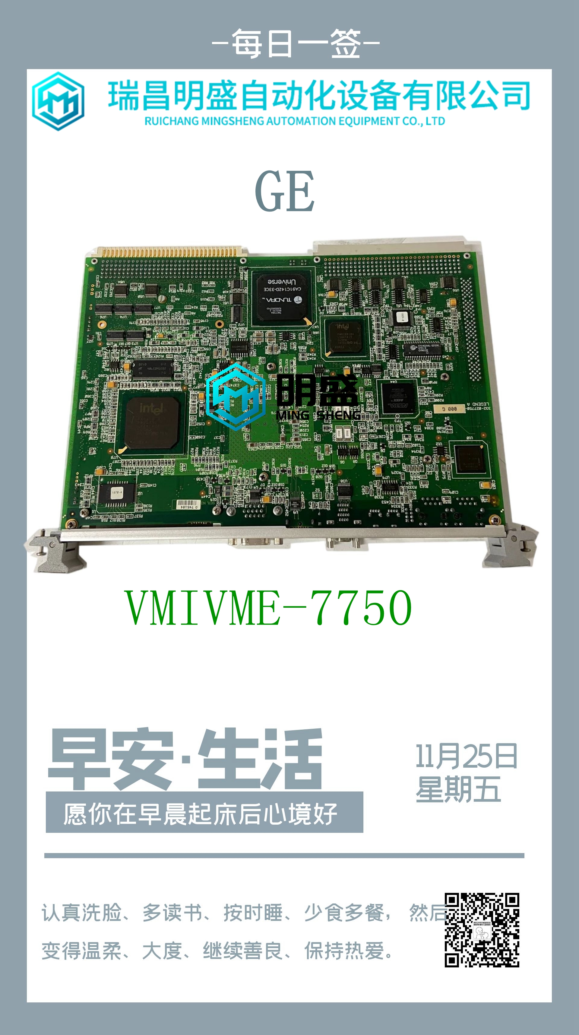
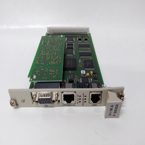
HIMA F4304機器人備件
PACSystems*RX3i系統手冊第3節GFK-2314T 2019年9月安裝30 0 1 2 3 4 5 6 7 8 9 10 11 12 E X P A N S I O N TB 1 1 8圖15:通用背板背板的安裝螺釘位置必須如上所示水平安裝,以通過在模塊周圍提供足夠的氣流來滿足產品性能和可靠性規范。其他安裝方向可能會影響系統性能、可靠性和機構批準,因此不建議使用。2.6.1.1.1通用背板端子TB1 RX3i IC695電源不通過背板提供隔離+24V直流輸出電源。TB1端子7和8可用于連接可選的隔離+24V直流外部電源(詳見第3.1.1.1節)。第4.2節“模塊負載要求”表中列出的一些IC693和IC694模塊需要隔離+24V直流電。這些端子接受14至22 AWG的單獨導線。如果需要隔離+24V直流的模塊安裝在擴展背板而不是通用背板中,則不需要外部隔離+24V dc電源。未使用端子1至6。1–6:未使用7:隔離+24V DC輸入8:隔離接地0 1 TB 1 1 8插槽0:僅用于RX3i IC695電源的連接器圖16:通用背板端子TB1 PACSystems*RX3i系統手冊第3節GFK-2314T 2019年9月安裝31 2.6.1.2電源型號和插槽占用電源目錄號#插槽占用1通用背板冗余模式遠程或擴展中最多占用1個背板IC695PSD040 1 1不支持不支持IC695PSD140 1 4 2支持不支持ICM695PSA040 2 1不支持IC69PSA140 2 4 2支持IC693電源不允許不允許N/A最多1個IC694電源不允許N/B最多1個2.6.1.3通用背板插槽占用規則? RX3i CPU模塊可以安裝在通用背板的任何位置,但最右側(擴展)插槽除外。除CPE302/CPE305外,CPU模塊占用2個插槽。CPE302和CPE305各自占據一個時隙。? CPE302、CPE305、I/O和選件模塊可以安裝在任何可用插槽中,但最右側(擴展)插槽和插槽0除外,后者只能接受IC695電源。每個I/O插槽有兩個連接器,因此可以接受基于RX3i PCI的模塊或帶有串行背板接口的模塊。? 最右邊的插槽是擴展插槽。它只能用于可選的串行總線發射器模塊IC695LRE001。2.6.2擴展背板要在面板上安裝擴展背板,請使用四個質量良好的8-32 x 1/2(4 x 12 mm)機器螺釘、鎖緊墊圈和平墊圈。將螺釘安裝到四個螺紋孔中。1個IC695電源模塊可以安裝在任何通用背板插槽中。2 IC695PSD140和IC695PSA140的任意組合,最多四個。PACSystems*RX3i系統手冊第3節GFK-2314T 2019年9月安裝32圖17:擴展背板也可以使用本節所述的安裝支架將擴展背板安裝在19英寸機架中。2.6.2.1設置機架編號DIP開關每個背板都用稱為機架編號的唯一編號標識。機架編號0始終自動分配給帶有CPU的背板。系統中不得重復機架編號。背板不需要按順序編號,但為了一致性,不應跳過機架編號。使用背板上的DIP開關設置擴展和遠程背板的機架編號。下表提供了用于選擇機架號的DIP開關位置。機架編號DIP開關1 2 3 4 5 6 7 1開-關-開-關,這些開關設置選擇機架號2:OPEN 1 2 3 Closed=右側開關關閉圖18:機架號PACSystems的背板DIP開關設置示例*RX3i系統手冊第3節GFK-2314T 2019年9月安裝33注意不要使用鉛筆設置DIP開關。鉛筆上的石墨會損壞開關。2.6.2.2擴展背板的建議安裝方向對于擴展和遠程背板,電源額定負載取決于背板的安裝位置和周圍溫度。在60°C(140°F)時,擴展背板直立安裝在面板上的額定負載為100%。
PACSystems* RX3i System Manual Section 3 GFK-2314T Sept. 2019 Installation 30 0 1 2 3 4 5 6 7 8 9 10 11 12 E X P A N S I O N TB 1 1 8 Figure 15: Location of Mounting Screws for Universal Backplane Backplanes must be mounted horizontally, as represented above, to meet product performance and reliability specifications by providing adequate airflow around the modules. Other mounting orientations may affect system performance, reliability and agency approvals, and are therefore not recommended. 2.6.1.1.1 Universal Backplane Terminal TB1 The RX3i IC695 Power Supplies do not provide Isolated +24Vdc output power over the backplane. TB1 Terminals 7 and 8 can be used to connect an optional external source of Isolated +24Vdc (see Section 3.1.1.1 for details). Isolated +24Vdc is required for some IC693 and IC694 modules as listed in the table of Module Load Requirements, Section 4.2. These terminals accept individual wires from 14 to 22 AWG. If modules that require Isolated +24Vdc are installed in an Expansion Backplane rather than in a Universal Backplane, an external Isolated +24Vdc power supply will not be required. Terminals 1 through 6 are not used. 1 – 6: not used 7: Isolated +24VDC In 8: Isolated Ground 0 1 TB 1 1 8 Slot 0: Connector for RX3i IC695 Power Supply only Figure 16: Universal Backplane Terminal TB1 PACSystems* RX3i System Manual Section 3 GFK-2314T Sept. 2019 Installation 31 2.6.1.2 Power Supply Models and Slot Occupancy Power Supply Catalog Number #Slots Occupied1 Max in Universal Backplane Redundant Mode Remote or Expansion Backplane IC695PSD040 1 1 Not supported Not supported IC695PSD140 1 4 2 Supported Not supported IC695PSA040 2 1 Not supported Not supported IC695PSA140 2 4 2 Supported Not supported IC693 Power Supplies Not permitted Not permitted N/A Max 1 IC694 Power Supplies Not permitted Not permitted N/A Max 1 2.6.1.3 Universal Backplane Slot Occupancy Rules ? An RX3i CPU module can be installed anywhere in the Universal Backplane except the rightmost (expansion) slot. With the exception of CPE302/CPE305, CPU modules occupy 2 slots. CPE302 and CPE305 each occupy one slot. ? CPE302, CPE305, I/O, and option modules can be installed in any available slot except the rightmost (expansion) slot and slot 0, which can only accept IC695 Power Supplies. Each I/O slot has two connectors, so can accept either an RX3i PCI-based module or a module with a serial backplane interface. ? The rightmost slot is the expansion slot. It can only be used for optional Serial Bus Transmitter module IC695LRE001. 2.6.2 Expansion Backplanes To mount an Expansion Backplane on a panel, use four good-quality 8-32 x 1/2 (4 x 12 mm) machine screws, lock washers and flat washers. Install the screws in the four tapped holes. 1 IC695 Power Supply modules may be installed in any Universal Backplane slot. 2 Any combination of IC695PSD140 & IC695PSA140, up to max of four. PACSystems* RX3i System Manual Section 3 GFK-2314T Sept. 2019 Installation 32 Figure 17: Expansion Backplane An Expansion Backplane can also be mounted in a 19-inch rack using a mounting bracket as described in this section. 2.6.2.1 Setting the Rack Number DIP Switch Each backplane is identified with a unique number called a Rack Number. Rack number 0 is always automatically assigned to the backplane with the CPU. Rack numbers must not be duplicated in a system. Backplanes do not need to be sequentially numbered, although for consistency, rack numbers should not be skipped. Rack Numbers for Expansion and Remote backplanes are set using a DIP switch on the backplane. The following table provides the DIP switch positions for rack number selection. Rack Number DIP Switch 1 2 3 4 5 6 7 1 open closed open closed open closed open 2 closed open open closed closed open open 3 closed closed closed open open open open For example, these switch settings select rack number 2: OPEN 1 2 3 Closed = switch down on right Figure 18: Example of Backplane DIP Switch Setting for Rack Number PACSystems* RX3i System Manual Section 3 GFK-2314T Sept. 2019 Installation 33 CAUTION Do not use a pencil to set the DIP switches. Graphite from the pencil can damage the switch. 2.6.2.2 Recommended Mounting Orientation for Expansion Backplanes For Expansion and Remote Backplanes, power supply load rating depends on the mounting position of the backplane and the surrounding temperature. The load rating with the Expansion Backplane mounted upright on a panel is100% at 60°C (140°F).


