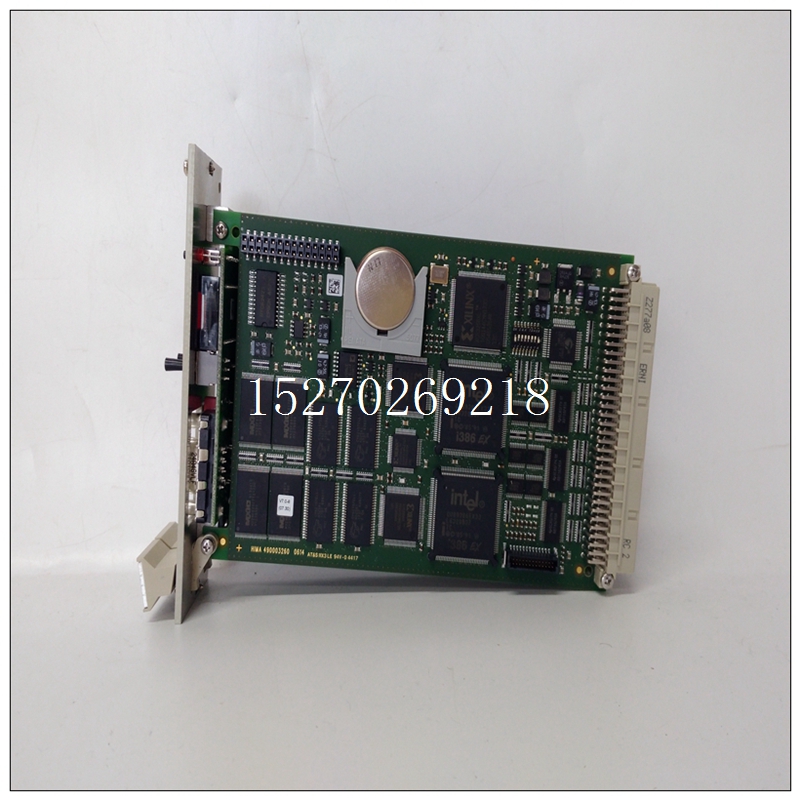
HIMA F6217 Z7127 模塊控制器
這對于未安裝在同一控制柜中的背板尤為重要。警告:除了遵守此處所述的接地程序外,還必須遵守當?shù)亟拥匾?guī)范。在美國,大多數(shù)地區(qū)都采用了國家電氣規(guī)范標準,并規(guī)定所有布線都符合其要求。在其他國家,適用不同的法規(guī)。為確保人員和財產(chǎn)的最大安全,請遵循這些規(guī)范。未能做到這一點可能意味著人員受傷或死亡、財產(chǎn)損失或兩者兼而有之。除了遵守系統(tǒng)接地程序外,還應定期檢查接地連接,以確保系統(tǒng)保持正確接地。? PLC設備、其他控制設備和機器應相互連接,以保持公共接地參考,也稱為機器底盤接地。PACSystems*RX3i系統(tǒng)手冊第3節(jié)GFK-2314T 2019年9月安裝27個中央接地點電機驅動器和其他電氣控制設備機器PLC機柜編程設備信號和電源連接未顯示注釋接地機架圖12:系統(tǒng)接地2.5.1接地導體應以樹形方式連接,并將分支布線至中心接地點,如前一頁所示。這確保了沒有接地導體從任何其他分支輸送電流。從系統(tǒng)所有部件到接地的低電感路徑可最大限度地減少排放,并提高對電氣干擾的免疫力。接地導體應盡可能短,尺寸盡可能大。可使用編織帶(建議最大長寬比為10:1)或接地電纜(通常為綠色絕緣,帶黃色示蹤物-AWG#12(3.3 mm2)或更大),以將電阻降至最低。導體必須始終足夠大,以承載所考慮路徑的最大短路電流。PACSystems*RX3i系統(tǒng)手冊第3節(jié)GFK-2314T 2019年9月安裝28 2.5.2背板安全和EMC參考接地背板的金屬背面必須使用單獨的導體接地;背板安裝螺釘本身不能提供足夠的接地連接。至少使用帶有環(huán)形端子和星形鎖緊墊圈的AWG#12(3.3 mm2)導線。使用機器螺釘、星形鎖緊墊圈和平墊圈將接地線的另一端連接到安裝面板上的螺紋孔。或者,如果面板有接地螺柱,則為接地螺上的每根導線使用螺母和星形鎖緊墊圈,以確保充分接地。當連接到涂漆面板時,應清除油漆,使其干凈,裸露金屬暴露在連接點。所用端子和硬件的額定值應與鋁背板材料配合使用。警告所有背板必須接地,以盡量減少觸電危險。否則可能導致嚴重的人身傷害。圖13:接地母線安裝PLC系統(tǒng)中組合在一起的所有背板必須具有公共接地連接。這對于未安裝在同一控制柜中的背板尤為重要。2.5.3電源接地參考“電源現(xiàn)場接線”一節(jié)。2.5.4編程器接地為了正常運行,運行PLC軟件的計算機(編程器)必須具有與CPU共用的接地連接。通常,這種公共接地連接是通過將編程設備的電源線連接到與背板相同的電源(具有相同的接地參考點)來實現(xiàn)的。如果編程器接地電位與PLC接地電位不同,則可能存在電擊危險。此外,當編程器串行電纜連接在兩者之間時,可能會損壞端口。2.5.5屏蔽接地PACSystems*RX3i系統(tǒng)手冊第3節(jié)GFK-2314T 2019年9月安裝29通常,鋁PLC背板用于模塊屏蔽接地。在某些模塊上,模塊上用戶終端連接器的屏蔽連接通過模塊的背板連接器路由到背板。其他模塊(如DSM314)需要單獨的屏蔽接地,如本手冊中的模塊說明所示。對于安裝在通用背板中的模塊,屏蔽接地可使用尺寸為M3的螺釘連接至背板底部的接地棒。建議的最大扭矩為0.45 Nm(4 in-lb)。RX3i通用背板2.6系統(tǒng)安裝2.6.1通用背板上的接地棒使用四個優(yōu)質8-32 x 1/2(4 x 12mm)機器螺釘、鎖緊墊圈和平墊圈安裝通用背板。將螺釘安裝在下圖所示的四個螺紋孔中。
This is especially important for backplanes that are not mounted in the same control cabinet. WARNING In addition to observing the grounding procedures described here, it is important to follow local grounding codes. In the United States, most areas have adopted the National Electrical Code standard and specify that all wiring conform to its requirements. In other countries, different codes apply. For maximum safety to personnel and property, follow these codes. Failure to do so can mean injury or death to personnel, damage to property, or both. In addition to observing the system grounding procedures, periodic inspections of the ground connections should be performed to ensure that the system remains properly grounded. ? The PLC equipment, other control equipment, and the machine should be interconnected to maintain a common earth ground reference, also called the machine chassis ground. PACSystems* RX3i System Manual Section 3 GFK-2314T Sept. 2019 Installation 27 CENTRAL GROUND POINT MOTOR DRIVES AND OTHER ELECTRICAL CONTROL EQUIPMENT MACHINERY PLC CABINET PROGRAMMING DEVICE SIGNAL AND POWER CONNECTIONS ARE NOT SHOWN NOTE EARTH GROUND RACK RACK Figure 12: System Grounding 2.5.1 Ground Conductors Ground conductors should be connected in a tree fashion with branches routed to a central earth ground point, as shown on the previous page. This ensures that no ground conductor carries current from any other branch. A low inductance path from all parts of a system to earth minimizes emissions and increases immunity to electrical interferences. Ground conductors should be as short and as large in size as possible. Braided straps (maximum 10:1 length to width ratio recommended) or ground cables (typically green insulation with a yellow tracer - AWG #12 (3.3 mm2 ) or larger) can be used to minimize resistance. Conductors must always be large enough to carry the maximum short circuit current of the path being considered. PACSystems* RX3i System Manual Section 3 GFK-2314T Sept. 2019 Installation 28 2.5.2 Backplane Safety and EMC Reference Grounding The metal back of the backplane must be grounded using a separate conductor; the backplane mounting screws alone do not provide an adequate ground connection. At a minimum, use AWG #12 (3.3 mm2 ) wire with a ring terminal and star lock-washer. Connect the other end of this ground wire to a tapped hole in the mounting panel using a machine screw, star lock washer, and flat washer. Alternately, if the panel has a ground stud, use a nut and star lock washer for each wire on the ground stud to ensure adequate grounding. Where connections are made to a painted panel, the paint should be removed so clean, bare metal is exposed at the connection point. Terminals and hardware used should be rated to work with the aluminum backplane material. WARNING All backplanes must be grounded to minimize electrical shock hazard. Failure to do so can result in severe personal injury. Figure 13: Ground Strap Installation All backplanes grouped together in the PLC system must have a common ground connection. This is especially important for backplanes that are not mounted in the same control cabinet. 2.5.3 Power Supply Grounding Refer to the section, Power Supply Field Wiring. 2.5.4 Programmer Grounding For proper operation, the computer (programmer) running the PLC software must have a ground connection in common with the CPU. Normally, this common ground connection is provided by connecting the power cord of the programming device to the same power source (with the same ground reference point) as the backplane. If the programmer ground is at a different potential than the PLC ground, a shock hazard could exist. Also, damage to the ports could occur when the programmer serial cable is connected between the two. 2.5.5 Shield Grounding PACSystems* RX3i System Manual Section 3 GFK-2314T Sept. 2019 Installation 29 In general, the aluminum PLC backplane is used for module shield grounding. On some modules, shield connections to the user terminal connector on the module are routed to the backplane through the backplane connector of the module. Other modules, such as the DSM314 require a separate shield ground, as displayed in the module descriptions in this manual. For modules installed in a Universal Backplane, shield grounds can be connected to the Grounding Bar at the bottom of the Backplane using size M3 screws. The recommended torque is 0.45 Nm (4 in-lb) maximum. Grounding Bar on RX3i Universal Backplane 2.6 System Installation 2.6.1 Universal Backplanes Mount a Universal Backplane using four good quality 8-32 x 1/2 (4 x 12mm) machine screws, lock washers and flat washers. Install the screws in the four tapped holes displayed in the following figure.


