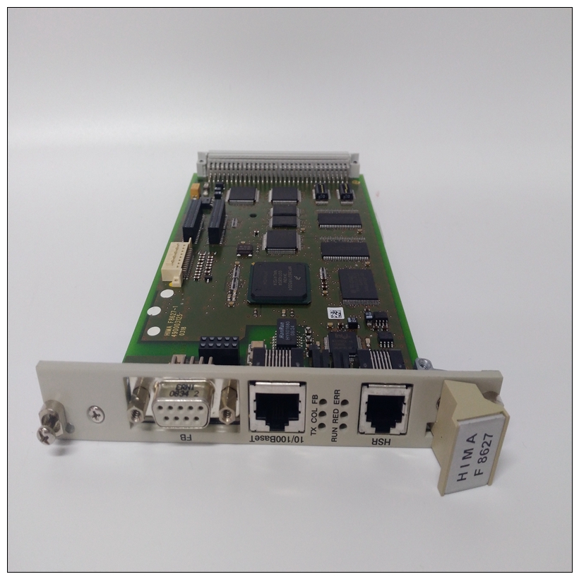
HIMA Z6011備件模塊,工控模塊
469僅支持RTU版本。使用讀寫寄存器命令可以實現監控、編程和控制功能。6.1.3數據幀格式和數據速率與469之間的異步傳輸的一個數據幀默認為1個起始位、8個數據位和1個停止位。這產生一個10位數據幀。這對于通過高比特率的調制解調器進行傳輸非常重要(在比特率大于300bps的情況下,Hayes調制解調器不支持11比特數據幀)。奇偶校驗位可選為奇數或偶數。如果編程為奇數或偶數,則數據幀由1個起始位、8個數據位、1個奇偶校驗位和1個停止位組成。Modbus協議可以以任何標準通信速度實現。469個RS485端口支持1200、2400、4800、9600和19200波特的操作。前面板RS232波特率固定為9600波特。6.1.4數據包格式完整的請求/響應序列由以下字節組成(作為單獨的數據幀傳輸):?從屬地址:這是每次傳輸的第一個字節。該字節表示接收主設備發送的消息的從屬設備的用戶分配地址。每個從設備必須被分配一個唯一的地址,并且只有被尋址的從設備響應以其地址開始的傳輸。在主請求傳輸中,從地址表示請求被發送到的從設備的地址。在從機響應傳輸中,從機地址表示發送響應的從機的地址。注意,從地址為0的主傳輸指示廣播命令。廣播命令可用于特定功能。主查詢消息:從屬地址:(1字節)功能代碼:(1個字節)數據:(取決于功能代碼的可變字節數)CRC:(2個字節)從屬響應消息:從屬位置:(1位字節)功能碼:(1)字節數據:(根據功能代碼的變化字節數)CRC:(2字節)6-2 469電機管理繼電器GE Multilin 6.1 MODBUS協議6通信6?功能代碼:此是每次傳輸的第二個字節。Modbus定義1至127的功能代碼。469實現了其中的一些功能。在主請求傳輸中,功能代碼告訴從設備要執行什么操作。在從機響應傳輸中,如果從機發送的功能碼與主機發送的指示從機按請求執行功能的功能碼相同。如果從設備發送的功能代碼的高位為1(即,如果功能代碼>127),則從設備未按要求執行功能,并發送錯誤或異常響應。?數據:取決于功能代碼的可變字節數。這可能是主設備向從設備發送的實際值、設置點或地址,反之亦然。數據首先發送MSByte,然后發送LSByte。?CRC:這是一個兩字節的錯誤檢查代碼。CRC首先發送LSByte,然后發送MSByte。Modbus的RTU版本包括每次傳輸的兩字節CRC-16(16位循環冗余檢查)。CRC-16算法本質上將整個數據流(僅數據位;忽略開始、停止和奇偶校驗)視為一個連續的二進制數。該數字首先左移16位,然后除以特征多項式(11000000000101B)。除法的16位剩余部分被附加到傳輸的末尾,首先是LSByte。如果沒有發生傳輸錯誤,則當在接收機處被相同多項式除時,包括CRC的結果消息將給出零余數。如果469 Modbus從設備接收到CRC-16計算指示錯誤的傳輸,則從設備不會對傳輸做出響應。CRC-16錯誤表示錯誤接收了傳輸的一個或多個字節,因此應忽略整個傳輸,以避免469執行任何錯誤操作。CRC-16計算是用于錯誤檢測的行業標準方法。在沒有標準CRC-16計算例程可用的情況下,這里包括一種算法來幫助程序員。6.1.5 CRC-16算法一旦完成以下算法,工作寄存器“A”將包含要傳輸的CRC值。注意,該算法要求特征多項式是反向位序的。特征多項式的MSbit被丟棄,因為它不影響余數的值。符號:-->數據傳輸A;阿羅;Ahigh 16位工作寄存器;A(16位工作寄存器)CRC 16位CRC-16結果的低位和高位字節i,j個循環計數器(+)邏輯異或運算符N數據字節總數Di第i個數據字節(i=0到N–1)G 16位特征多項式=1010000000000001(二進制),刪除MSbit并按位序
Only the RTU version is supported by the 469. Monitoring, programming and control functions are possible using read and write register commands. 6.1.3 DATA FRAME FORMAT AND DATA RATE One data frame of an asynchronous transmission to or from an 469 is default to 1 start bit, 8 data bits, and 1 stop bit. This produces a 10 bit data frame. This is important for transmission through modems at high bit rates (11-bit data frames are not supported by Hayes modems at bit rates of greater than 300 bps). The parity bit is optional as odd or even. If it is programmed as odd or even, the data frame consists of 1 start bit, 8 data bits, 1 parity bit, and 1 stop bit. Modbus protocol can be implemented at any standard communication speed. The 469 RS485 ports support operation at 1200, 2400, 4800, 9600, and 19200 baud. The front panel RS232 baud rate is fixed at 9600 baud. 6.1.4 DATA PACKET FORMAT A complete request/response sequence consists of the following bytes (transmitted as separate data frames): ? SLAVE ADDRESS: This is the first byte of every transmission. This byte represents the user-assigned address of the slave device that receives the message sent by the master. Each slave device must be assigned a unique address and only the addressed slave responds to a transmission that starts with its address. In a master request transmission the Slave Address represents the address of the slave to which the request is being sent. In a slave response transmission the Slave Address represents the address of the slave that is sending the response. Note that a master transmission with a Slave Address of 0 indicates a broadcast command. Broadcast commands can be used for specific functions. MASTER QUERY MESSAGE: SLAVE ADDRESS: (1 byte) FUNCTION CODE: (1 byte) DATA: (variable number of bytes depending on FUNCTION CODE) CRC: (2 bytes) SLAVE RESPONSE MESSAGE: SLAVE ADDRESS: (1 byte) FUNCTION CODE: (1 byte) DATA: (variable number of bytes depending on FUNCTION CODE) CRC: (2 bytes) 6-2 469 Motor Management Relay GE Multilin 6.1 MODBUS PROTOCOL 6 COMMUNICATIONS 6 ? FUNCTION CODE: This is the second byte of every transmission. Modbus defines function codes of 1 to 127. The 469 implements some of these functions. In a master request transmission the Function Code tells the slave what action to perform. In a slave response transmission if the Function Code sent from the slave is the same as the Function Code sent from the master indicating the slave performed the function as requested. If the high order bit of the Function Code sent from the slave is a 1 (i.e. if the Function Code is > 127) then the slave did not perform the function as requested and is sending an error or exception response. ? DATA: A variable number of bytes depending on the Function Code. This may be actual values, setpoints, or addresses sent by the master to the slave or vice versa. Data is sent MSByte first followed by the LSByte. ? CRC: This is a two byte error checking code. CRC is sent LSByte first followed by the MSByte. The RTU version of Modbus includes a two byte CRC-16 (16-bit cyclic redundancy check) with every transmission. The CRC-16 algorithm essentially treats the entire data stream (data bits only; start, stop and parity ignored) as one continuous binary number. This number is first shifted left 16 bits and then divided by a characteristic polynomial (11000000000000101B). The 16-bit remainder of the division is appended to the end of the transmission, LSByte first. The resulting message including CRC, when divided by the same polynomial at the receiver will give a zero remainder if no transmission errors have occurred. If an 469 Modbus slave device receives a transmission in which an error is indicated by the CRC-16 calculation, the slave device will not respond to the transmission. A CRC-16 error indicates than one or more bytes of the transmission were received incorrectly and thus the entire transmission should be ignored in order to avoid the 469 performing any incorrect operation. The CRC-16 calculation is an industry standard method used for error detection. An algorithm is included here to assist programmers in situations where no standard CRC-16 calculation routines are available. 6.1.5 CRC-16 ALGORITHM Once the following algorithm is complete, the working register "A" will contain the CRC value to be transmitted. Note that this algorithm requires the characteristic polynomial to be reverse bit ordered. The MSbit of the characteristic polynomial is dropped since it does not affect the value of the remainder. Symbols: --> data transfer A; Alow; Ahigh 16-bit working register; low and high order bytes of A (the 16-bit working register) CRC 16 bit CRC-16 result i, j loop counters (+) logical EXCLUSIVE-OR operator N total number of data bytes Di i-th data byte (i = 0 to N – 1) G 16 bit characteristic polynomial = 1010000000000001 (binary) with MSbit dropped and bit order


