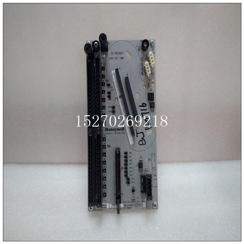
HONEYWELL 51405047-175 CC-PCF901工控模塊機器人備件
跳閘和輔助設備2、跳閘和輔助2和輔助3;跳閘和輔助3機械卡阻傳感器:1.50 x FLA范圍:1.01至3.00 x FLA,步長為0.01機械卡阻延遲:1秒范圍:1至30秒,步長為1 ENTER ESCAPE(進入)ESCAPE,(退出)MESSAGE ESCAPE MESSAGE ESCAPE(退出)MISSAGE ESCAP MESSAGE(退出信息)ESCAPE RESET ENTER ESCAPE,(退出信息重置)MESSAG ESCAPE ESCAPE-MESSAGE,(進入退出信息)MESSAGE-ESCAPE信息)ESCAP,(退出消息)4-44 469電機管理繼電器GE Multilin 4.7 S6電流元件4設定點4 4.7.4欠電流路徑:設定值×S6電流元件×欠電流一旦Ia、Ib或Ic值在欠電流報警延遲規定的時間內低于拾取電平×FLA,就會發生跳閘或報警。欠電流元件僅在電機運行時激活。在電機啟動啟動時,在U/C BLOCK FROM start(U/C阻止啟動)設定點規定的時間內將其阻斷(例如,該阻斷可用于允許泵在欠流元件跳閘之前建立揚程)。值“0”表示該功能從開始時未被阻止。如果輸入的值不是“0”,則當電機停止時,以及從檢測到啟動到輸入的時間結束時,該功能將被禁用。在正常操作期間,欠電流報警拾取水平應設置為低于電機負載。例如,如果泵被其泵送的液體冷卻,則負載損失可能意味著泵過熱。在這種情況下,啟用欠流功能。如果電機負載永遠不會低于0.75×FLA,即使在短時間內,欠電流跳閘傳感器也可以設置為“0.70”,欠電流報警傳感器設置為“0.75”。如果泵始終啟動負載,則應禁用“從啟動開始阻止欠電流”設定點(編程為0)欠電流報警延遲/欠電流跳閘延遲通常設置得盡可能快,即1秒。n欠電流n[ENTER]表示更多的BLOCK UNDERCURRENT FROM START:0秒范圍:0到15000秒,步長為1欠電流報警:關閉范圍:關閉、鎖定、未鎖定分配報警繼電器:報警范圍:報警、報警和輔助2、報警和輔2和輔助3、輔助2、輔2和輔3,輔助3欠電流報警拾取:0.70 x FLA范圍:0.10至0.95 x FLA,步長為0.01欠電流報警延遲:1秒范圍:1至60秒,步長為1欠電流報警事件:關閉范圍:打開,關閉欠電流跳閘:關閉范圍,鎖定,未鎖定分配跳閘繼電器:跳閘范圍:跳閘,跳閘&輔助2,跳閘&輔2&輔3,跳閘和輔助3欠電流跳閘傳感器:0.70 x FLA范圍:0.10至0.99 x FLA,步長為0.01欠電流跳閘延遲:1 s范圍:1至60 s,步長為1 ENTER ESCAPE(輸入退出)4.7.5電流不平衡路徑:如果電機在大于FLA的負載(Iavg)下運行,則設定點×S6電流元件×電流不平衡469定義為負序電流與正序電流之比I2/I1。如果電機Iavg小于FLA,則不平衡定義為I2/I1×Iavg/FLA。這種降額是必要的,以防止電機負載較輕時發出有害警報。如果啟用,當不平衡量值超過CURRENT unbalance alarm_x0012_trip PICKUP(當前不平衡報警_x0012_跳閘延遲)指定的時間段時,會發生跳閘和/或報警。如果不平衡水平超過40%,或當Iavg>25%FLA且任何一相的電流為零時,電機被視為單相,并在2秒內跳閘。如果不平衡功能被“關閉”,則單相保護被禁用。當設置CURRENT UNBALANCE ALARM_x0012_TRIP PICKUP(電流不平衡報警_x0012_跳閘拾取)級別時,請注意,1%的電壓不平衡通常會轉化為6%的電流不平衡。因此,為了防止意外跳閘或報警,拾取水平不應設置得太低。此外,由于短期不平衡是常見的,因此應設置合理的延遲,以避免產生干擾性跳閘或警報。建議使用不平衡偏置特性來偏置由周期性短期不平衡引起的電機加熱熱模型(見第4–38頁第d節:不平衡偏置)。異常高的不平衡水平可能由不正確的相位CT接線引起。例如,電流不平衡水平的波動通常由電源電壓引起。可能需要有一個鎖存報警,以捕捉超出不平衡報警參數的任何此類波動。此外,建議旅行。如果電源電壓通常不平衡達2%,典型電機的電流不平衡為2×6=12%。在這種情況下,將電流不平衡報警傳感器設置為“15”,電流不平衡跳閘傳感器設置為”20”,以防止意外跳閘;5或10秒是合理的延遲。
Trip & Auxiliary2, Trip & Aux2 & Aux3; Trip & Auxiliary3 MECHANICAL JAM PICKUP: 1.50 x FLA Range: 1.01 to 3.00 x FLA in steps of 0.01 MECHANICAL JAM DELAY: 1 s Range: 1 to 30 s in steps of 1 ENTER ESCAPE e e MESSAGE ESCAPE MESSAGE ESCAPE MESSAGE ESCAPE RESET ENTER ESCAPE e e MESSAGE ESCAPE MESSAGE ESCAPE MESSAGE ESCAPE 4-44 469 Motor Management Relay GE Multilin 4.7 S6 CURRENT ELEMENTS 4 SETPOINTS 4 4.7.4 UNDERCURRENT PATH: SETPOINTS ?× S6 CURRENT ELEMENTS ?× UNDERCURRENT A trip or alarm will occurs once the magnitude Ia, Ib, or Ic falls below the pickup level × FLA for the time specified by the UNDERCURRENT ALARM DELAY. The Undercurrent element is active only when the motor is running. It is blocked upon the initiation of a motor start for the time defined by the U/C BLOCK FROM START setpoint (e.g. this block may be used to allow pumps to build up head before the undercurrent element trips). A value of "0" means the feature is not blocked from start. If a value other than "0" is entered, the feature is disabled when the motor is stopped and also from the time a start is detected until the time entered expires. The UNDERCURRENT ALARM PICKUP level should be set lower than motor loading during normal operations. For example, if a pump is cooled by the liquid it pumps, loss of load may mean that the pump overheats. In this case, enable the undercurrent feature. If the motor loading should never fall below 0.75 × FLA, even for short durations, the UNDERCURRENT TRIP PICKUP could be set to "0.70" and the UNDERCURRENT ALARM PICKUP to "0.75". If the pump is always started loaded, the BLOCK UNDERCURRENT FROM START setpoint should be disabled (programmed as 0). ? the UNDERCURRENT ALARM DELAY / UNDERCURRENT TRIP DELAY is typically set as quick as possible, i.e. 1 s. n UNDERCURRENT n [ENTER] for more BLOCK UNDERCURRENT FROM START: 0 s Range: 0 to 15000 s in steps of 1 UNDERCURRENT ALARM: Off Range: Off, Latched, Unlatched ASSIGN ALARM RELAYS: Alarm Range: Alarm, Alarm & Auxiliary2, Alarm & Aux2 & Aux3, Auxiliary2, Aux2 & Aux3, Auxiliary3 UNDERCURRENT ALARM PICKUP: 0.70 x FLA Range: 0.10 to 0.95 x FLA in steps of 0.01 UNDERCURRENT ALARM DELAY: 1 s Range: 1 to 60 s in steps of 1 UNDERCURRENT ALARM EVENTS: Off Range: On, Off UNDERCURRENT TRIP: Off Range: Off, Latched, Unlatched ASSIGN TRIP RELAYS: Trip Range: Trip, Trip & Auxiliary2, Trip & Aux2 & Aux3, Trip & Auxiliary3 UNDERCURRENT TRIP PICKUP: 0.70 x FLA Range: 0.10 to 0.99 x FLA in steps of 0.01 UNDERCURRENT TRIP DELAY: 1 s Range: 1 to 60 s in steps of 1 ENTER ESCAPE e e MESSAGE ESCAPE MESSAGE ESCAPE MESSAGE ESCAPE MESSAGE ESCAPE MESSAGE ESCAPE MESSAGE ESCAPE MESSAGE ESCAPE MESSAGE ESCAPE MESSAGE ESCAPE GE Multilin 469 Motor Management Relay 4-45 4 SETPOINTS 4.7 S6 CURRENT ELEMENTS 4 4.7.5 CURRENT UNBALANCE PATH: SETPOINTS ?× S6 CURRENT ELEMENTS ?× CURRENT UNBALANCE 469 unbalance is defined as the ratio of negative-sequence to positive-sequence current, I2 / I1, if the motor is operating at a load (Iavg) greater than FLA. If the motor Iavg is less than FLA, unbalance is defined as I2 / I1 × Iavg / FLA. This derating is necessary to prevent nuisance alarms when a motor is lightly loaded. If enabled, a trip and/or alarm occurs once the unbalance magnitude exceeds the CURRENT UNBALANCE ALARM_x0012_TRIP PICKUP for a period of time specified by the CURRENT UNBALANCE ALARM_x0012_TRIP DELAY. If the unbalance level exceeds 40%, or when Iavg > 25% FLA and current in any one phase is zero, the motor is considered single phasing and a trip occurs within 2 seconds. Single phasing protection is disabled if the unbalance feature is turned "Off". When setting the CURRENT UNBALANCE ALARM_x0012_TRIP PICKUP level, note that a 1% voltage unbalance typically translates into a 6% current unbalance. Therefore, to prevent nuisance trips or alarms, the pickup level should not be set too low. Also, since short term unbalances are common, a reasonable delay should be set to avoid nuisance trips or alarms. The unbalance bias feature is recommended to bias the thermal model for motor heating caused by cyclic short term unbalances (see Section d): Unbalance Bias on page 4–38). Unusually high unbalance levels may be caused by incorrect phase CT wiring. For example, fluctuations of current unbalance levels are typically caused by the supply voltage. It may be desirable to have a latched alarm to capture any such fluctuations that go beyond the Unbalance Alarm parameters. Also, a trip is recommended. If the supply voltage is normally unbalanced up to 2%, the current unbalance seen by a typical motor is 2 × 6 = 12%. In this case, set the CURRENT UNBALANCE ALARM PICKUP to "15" and the CURRENT UNBALANCE TRIP PICKUP to "20" to prevent nuisance tripping; 5 or 10 seconds is a reasonable delay.


