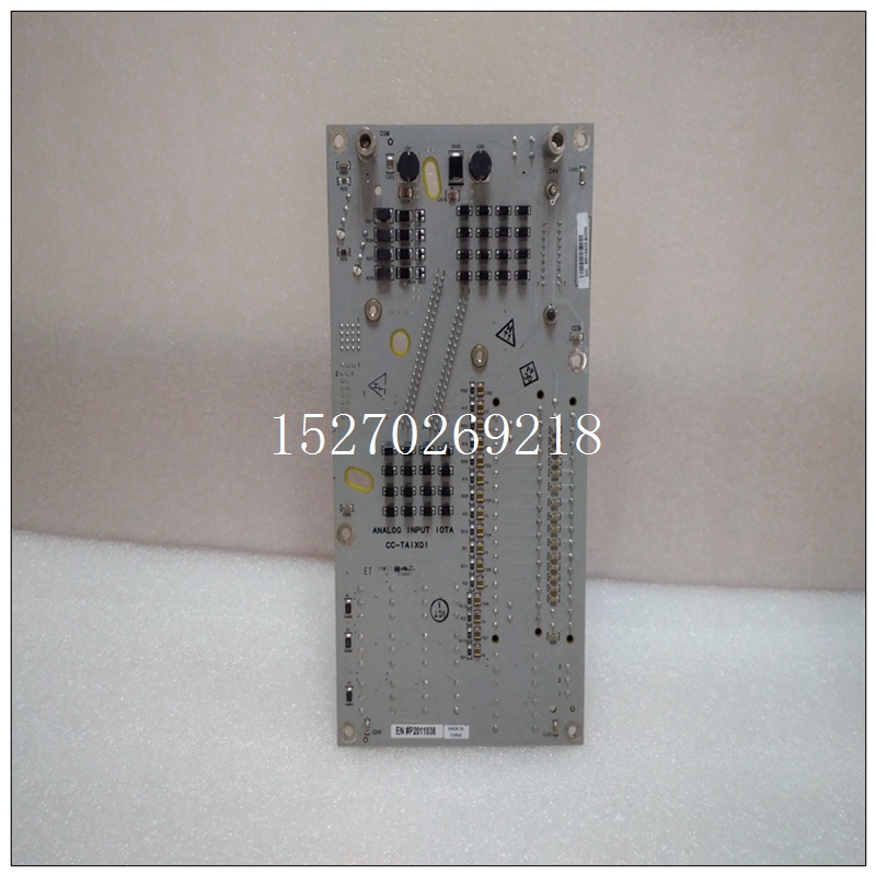
HONEYWELL CC-TAON11自動化模塊備件
t例如玻璃瓶。探頭可由輸入開關電源的+24 V供電。NPN晶體管的輸出可以被帶到配置為計數器的可分配數字輸入之一。n ASSIGNABLE INPUT 1 n[ENTER]了解更多INPUT 1 FUNCTION:數字計數器范圍:見上文。只有當輸入1(4)功能為“數字計數器”時,以下設置點才適用。計數器單位:單位范圍:6個字母數字字符。僅當INPUT 1(4)FUNCTION為“數字計數器”Counter PRESET VALUE:0范圍:0到1000000000,步長為1時才可見。僅當輸入1(4)功能為“數字計數器”計數器類型:遞增范圍:遞增、遞減時才可見。僅當輸入1(4)功能為“數字計數器”計數器報警:關閉范圍:關閉、鎖定、未鎖定時才可見。僅當輸入1(4)功能為“數字計數器”時才可見,分配報警繼電器:報警范圍:報警、報警和輔助2、報警和輔2、報警與輔助3、報警與輔3、輔助2、輔助2和輔助3、輔助3。僅當輸入1(4)功能為“數字計數器”計數器報警級別:100范圍:0至1000000000,步長為1時才可見。僅當輸入1(4)功能為“數字計數器”計數器報警拾取:超出范圍:超過、低于時才可見。僅當輸入1(4)功能為“數字計數器”計數器報警事件:關閉范圍:開、關時才可見。僅當輸入1(4)功能為“數字計數器”時,才顯示ENTER ESCAPE(輸入ESCAPE)輸入ESCAPE(輸出ESCAPE信息)輸入ESCCAPE(輸出ESCAP信息)輸入ESCAPE(輸出ESCAPE信息對于其中一個可分配的數字輸入,此處顯示的設置點消息將跟隨分配消息。測量每個開關閉合之間的時間段,并根據每轉一次閉合轉換為RPM值。可以配置跳閘和警報,使得電機或負載必須在電機啟動開始后的設定時間段內處于一定速度。電機停止時,轉速計跳閘和報警被忽略。RPM值可與A2 METERING?SPEED?轉速表實際值一起查看。例如,感應接近探頭或霍爾效應齒輪齒傳感器可用于感應電機上的鑰匙。探頭可由輸入開關電源的+24 V供電。NPN晶體管輸出可被帶到配置為轉速表的可分配開關輸入之一。n ASSIGNABLE INPUT 1 n[ENTER]了解更多輸入1功能:轉速表范圍:見上文。只有當輸入1(4)功能為“轉速計”時,以下設定點才適用。額定轉速:3600 RPM范圍:100至7200 RPM,步長為1。僅當輸入1(4)功能為“轉速表”轉速表報警:關閉范圍:關閉、鎖定、未鎖定時才可見。僅當輸入1(4)功能為“轉速計”時可見,分配報警繼電器:報警范圍:報警、報警和輔助2、報警和輔2和輔3、報警和副3、輔助2、輔助2和輔助3、輔助3。僅當輸入1(4)功能為“轉速計”轉速計報警速度:10%額定范圍:5至100%,步長為1時可見。僅當輸入1(4)功能為“轉速表”轉速表報警延遲:1 s范圍:1到250 s,步長為1。僅當輸入1(4)功能為“轉速計”轉速計報警事件:關閉范圍:開、關時可見。僅當輸入2(4)函數為“轉速表”轉速計跳閘:關閉范圍,鎖定,未鎖定時可見。僅當輸入1(4)功能為“轉速計”時才可見,指定跳閘繼電器:跳閘范圍:跳閘、跳閘和輔助2、跳閘與輔助2和輔助3、跳閘與輔3。僅當輸入1(4)功能為“轉速表”轉速表跳閘速度:10%額定范圍:5至95%,步長為1。僅當輸入1(4)功能為“轉速表”轉速表跳閘延遲:1 s范圍:1到250 s,步長為1。僅當輸入1(4)功能為“轉速計”時才可見,輸入ESCAPE(轉速計)ENTER ESCAPE?信息ESCAPE MESSAGE ESCAPE ESCAPE MESSAGE ESCAPE MESTAGE ESCAPEMESSAGE ESCAPE ESCAP MESSAGE(轉速表)MESSAGE ESC APE ESCAPE MESSAGE DESSAGE ESCAP(轉速計功能)輸入ESCAPE-ESCAPE信息ESCAPEMISSAGE ESCCAPE(轉速傳感器)MESSAG ESCAPE ESCAPE MESPAGE ESCAPES ESCAPE RESSAGE ESCRAPE ESCAPE-MESSAGE信息ESCAP(速度計)功能4-24 469電機管理繼電器GE Multilin 4.4 S3數字輸入4設定點是可分配給四個可分配數字輸入中的任何一個的四個通用開關功能。一旦為其中一個數字輸入選擇了通用開關功能,此處顯示的設置點消息將跟隨分配消息。然后可以為該輸入配置警報和/或跳閘。如果需要,可為警報和/或跳閘分配一個通用名稱和一個從電機啟動開始的通用阻斷時間(如果在電機啟動后一段時間內禁用警報)。BLOCK的值為“0”
hat are passing by on a conveyor, glass bottles for instance. The probe could be powered from the +24 V from the input switch power supply. The NPN transistor output could be taken to one of the assignable digital inputs configured as a counter. n ASSIGNABLE INPUT 1 n [ENTER] for more INPUT 1 FUNCTION: Digital Counter Range: See above. The following setpoints apply only if INPUT 1(4) FUNCTION is “Digital Counter”. COUNTER UNITS: Units Range: 6 alphanumeric characters. Only seen if INPUT 1(4) FUNCTION is “Digital Counter” COUNTER PRESET VALUE: 0 Range: 0 to 1000000000 in steps of 1. Only seen if INPUT 1(4) FUNCTION is “Digital Counter” COUNTER TYPE: Increment Range: Increment, Decrement. Only seen if INPUT 1(4) FUNCTION is “Digital Counter” COUNTER ALARM: Off Range: Off, Latched, Unlatched. Only seen if INPUT 1(4) FUNCTION is “Digital Counter” ASSIGN ALARM RELAYS: Alarm Range: Alarm, Alarm & Auxiliary2, Alarm & Aux2 & Aux3, Alarm & Auxiliary3, Auxiliary2, Aux2 & Aux3, Auxiliary3. Only seen if INPUT 1(4) FUNCTION is “Digital Counter” COUNTER ALARM LEVEL: 100 Range: 0 to 1000000000 in steps of 1. Only seen if INPUT 1(4) FUNCTION is “Digital Counter” COUNTER ALARM PICKUP: Over Range: Over, Under. Only seen if INPUT 1(4) FUNCTION is “Digital Counter” COUNTER ALARM EVENTS: Off Range: On, Off. Only seen if INPUT 1(4) FUNCTION is “Digital Counter” ENTER ESCAPE e e MESSAGE ESCAPE MESSAGE ESCAPE MESSAGE ESCAPE MESSAGE ESCAPE MESSAGE ESCAPE MESSAGE ESCAPE MESSAGE ESCAPE MESSAGE ESCAPE GE Multilin 469 Motor Management Relay 4-23 4 SETPOINTS 4.4 S3 DIGITAL INPUTS 4 k) TACHOMETER PATH: SETPOINTS ?× S3 DIGITAL INPUTS ?× ASSIGNABLE INPUT 1(4) Once the tachometer function is chosen for one of the assignable digital inputs, the setpoint messages shown here will follow the assignment message. The period of time between each switch closure measured and converted to an RPM value based on one closure per revolution. A trip and alarm may be configured such that the motor or load must be at a certain speed within a set period of time from the initiation of motor starting. The tachometer trip and alarm are ignored while the motor is stopped. The RPM value may be viewed with the A2 METERING ?× SPEED ? TACHOMETER actual value. For example, an inductive proximity probe or hall effect gear tooth sensor may be used to sense the key on the motor. The probe could be powered from the +24 V from the input switch power supply. The NPN transistor output could be taken to one of the assignable switch inputs configured as a tachometer. n ASSIGNABLE INPUT 1 n [ENTER] for more INPUT 1 FUNCTION: Tachometer Range: See above. The following setpoints apply only if INPUT 1(4) FUNCTION is “Tachometer”. RATED SPEED: 3600 RPM Range: 100 to 7200 RPM in steps of 1. Only seen if INPUT 1(4) FUNCTION is “Tachometer” TACHOMETER ALARM: Off Range: Off, Latched, Unlatched. Only seen if INPUT 1(4) FUNCTION is “Tachometer” ASSIGN ALARM RELAYS: Alarm Range: Alarm, Alarm & Auxiliary2, Alarm & Aux2 & Aux3, Alarm & Auxiliary3, Auxiliary2, Aux2 & Aux3, Auxiliary3. Only seen if INPUT 1(4) FUNCTION is “Tachometer” TACHOMETER ALARM SPEED: 10% Rated Range: 5 to 100% in steps of 1. Only seen if INPUT 1(4) FUNCTION is “Tachometer” TACHOMETER ALARM DELAY: 1 s Range: 1 to 250 s in steps of 1. Only seen if INPUT 1(4) FUNCTION is “Tachometer” TACHOMETER ALARM EVENTS: Off Range: On, Off. Only seen if INPUT 1(4) FUNCTION is “Tachometer” TACHOMETER TRIP: Off Range: Off, Latched, Unlatched. Only seen if INPUT 1(4) FUNCTION is “Tachometer” ASSIGN TRIP RELAYS: Trip Range: Trip, Trip & Auxiliary2, Trip & Aux2 & Aux3, Trip & Auxiliary3. Only seen if INPUT 1(4) FUNCTION is “Tachometer” TACHOMETER TRIP SPEED: 10% Rated Range: 5 to 95% in steps of 1. Only seen if INPUT 1(4) FUNCTION is “Tachometer” TACHOMETER TRIP DELAY: 1 s Range: 1 to 250 s in steps of 1. Only seen if INPUT 1(4) FUNCTION is “Tachometer” ENTER ESCAPE e e MESSAGE ESCAPE MESSAGE ESCAPE MESSAGE ESCAPE MESSAGE ESCAPE MESSAGE ESCAPE MESSAGE ESCAPE MESSAGE ESCAPE MESSAGE ESCAPE MESSAGE ESCAPE MESSAGE ESCAPE 4-24 469 Motor Management Relay GE Multilin 4.4 S3 DIGITAL INPUTS 4 SETPOINTS 4 l) GENERAL SWITCH A to D PATH: SETPOINTS ?× S3 DIGITAL INPUTS ?× ASSIGNABLE INPUT 1(4) There are four General Switch functions assignable to any of the four assignable digital inputs. Once a General Switch function is chosen for one of the digital inputs, the setpoint messages shown here follow the assignment message. An alarm and/or trip may then be configured for that input. The alarm and/or trip may be assigned a common name and a common block time from motor start if required (if the alarm is to be disabled until some period of time after he motor has been started). A value of "0" for the BLOCK


