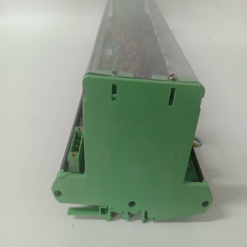
ICS TRIPLEX T3510模塊備件,備件模塊
裝置標簽詳細說明了以下信息:?型號?類型?序列號?制造日期?相電流輸入?特別說明?過電壓類別?絕緣電壓?污染程度?控制功率?輸出觸點額定值圖2-3:外殼和裝置識別標簽GE Multilin 469電機管理繼電器2-3 2安裝2.1機械2 2.1.3安裝469機箱,單獨或與另一個SR系列單元相鄰,可安裝在標準19英寸機架的面板中(面板切口尺寸見下圖)。安裝前門時,必須做好準備,使其在不干擾相鄰設備的情況下打開。通常情況下,469裝置在出廠時安裝在外殼中,在將外殼安裝在支撐面板中之前,應將其拆下。下一節將描述單元的撤回。圖2-4:單469和雙469切割面板準備好面板中的安裝孔后,從前面將469外殼滑入面板。在前面板上施加牢固的壓力,以確保前擋板緊貼面板的前部,如下圖所示,從外殼的每一側彎曲一對固定凸舌(至水平位置)。機箱現已牢固安裝,可用于面板布線。如果需要額外的支撐,可以訂購SR可選安裝套件。圖2–5:彎起安裝片單斷流器面板雙斷流器面板808704A1.CDR 2-4 469電機管理繼電器GE Multilin 2.1機械2安裝2 2.1.4單元抽出和插入在拉出或重新插入繼電器之前關閉控制電源,以防止誤操作!如果試圖將裝置安裝到不匹配的外殼中,機械鑰匙將阻止裝置完全插入。在以下步驟中不要用力,否則可能會造成損壞。要從機箱中卸下單元:1。抓住右側的中心,然后拉動蓋子,打開蓋子,蓋子將圍繞左側的鉸鏈旋轉。2.用螺絲刀向上按壓鎖閂,松開位于鎖柄下方的鎖閂。圖2-6:按下鎖閂以松開手柄3。將鎖閂抬起時,抓住中央的鎖定手柄并用力拉動,將手柄從裝置底部向上旋轉,直到停止移動。圖2-7:旋轉手柄至停止位置注意事項GE Multilin 469電機管理繼電器2-5 2安裝2.1機械2 4。一旦手柄從鎖定機構釋放,當手柄拉動時,裝置可以自由滑出外殼。有時可能需要稍微調整手柄位置以釋放裝置。圖2-8:將裝置滑出外殼將裝置插入外殼:1。將鎖定手柄升至最高位置。2.將裝置直接固定在機箱前面,并將滾動導向銷(靠近鎖定手柄的鉸鏈)與機箱兩側的導向槽對齊。3.將裝置滑入外殼,直到裝置上的導向銷
unit label details the following information: ? MODEL NUMBER ? TYPE ? SERIAL NUMBER ? MANUFACTURE DATE ? PHASE CURRENT INPUTS ? SPECIAL NOTES ? OVERVOLTAGE CATEGORY ? INSULATION VOLTAGE ? POLLUTION DEGREE ? CONTROL POWER ? OUTPUT CONTACT RATING Figure 2–3: CASE AND UNIT IDENTIFICATION LABELS GE Multilin 469 Motor Management Relay 2-3 2 INSTALLATION 2.1 MECHANICAL 2 2.1.3 INSTALLATION The 469 case, alone or adjacent to another SR series unit, can be installed in the panel of a standard 19-inch rack (see the diagram below for panel cutout dimensions). Provision must be made when mounting for the front door to swing open without interference to, or from, adjacent equipment. Normally the 469 unit is mounted in its case when shipped from the factory, and should be removed before mounting the case in the supporting panel. Unit withdrawal is described in the next section. Figure 2–4: SINGLE AND DOUBLE 469 CUTOUT PANELS After the mounting hole in the panel has been prepared, slide the 469 case into the panel from the front. Applying firm pressure on the front to ensure the front bezel fits snugly against the front of the panel, bend out the pair of retaining tabs (to a horizontal position) from each side of the case as shown below. The case is now securely mounted, ready for panel wiring. If additional support is desired, the SR optional mounting kit may be ordered. Figure 2–5: BEND UP MOUNTING TABS Single Cutout Panel Double Cutout Panel 808704A1.CDR 2-4 469 Motor Management Relay GE Multilin 2.1 MECHANICAL 2 INSTALLATION 2 2.1.4 UNIT WITHDRAWAL AND INSERTION TURN OFF CONTROL POWER BEFORE DRAWING OUT OR RE-INSERTING THE RELAY TO PREVENT MALOPERATION! If an attempt is made to install a unit into a non-matching case, the mechanical key will prevent full insertion of the unit. Do not apply strong force in the following step or damage may result. To remove the unit from the case: 1. Open the cover by grasping the center of the right side and then pulling the cover, which will rotate about the hinges on the left. 2. Release the locking latch, located below the locking handle, by pressing upward on the latch with the tip of a screwdriver. Figure 2–6: PRESS LATCH TO DISENGAGE HANDLE 3. While holding the latch raised, grasp the locking handle in the center and pull firmly, rotating the handle up from the bottom of the unit until movement ceases. Figure 2–7: ROTATE HANDLE TO STOP POSITION CAUTION CAUTION GE Multilin 469 Motor Management Relay 2-5 2 INSTALLATION 2.1 MECHANICAL 2 4. Once the handle is released from the locking mechanism, the unit can freely slide out of the case when pulled by the handle. It may sometimes be necessary to adjust the handle position slightly to free the unit. Figure 2–8: SLIDE UNIT OUT OF CASE To insert the unit into the case: 1. Raise the locking handle to the highest position. 2. Hold the unit immediately in front of the case and align the rolling guide pins (near the hinges of the locking handle) to the guide slots on either side of the case. 3. Slide the unit into the case until the guide pins on the unit have


