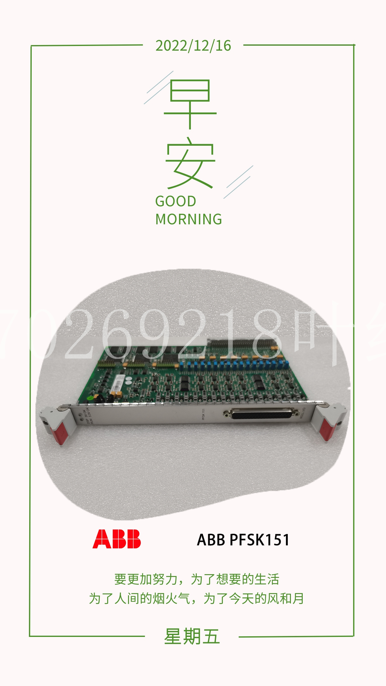
ICS TRIPLEX T8913工控模塊機器人備件
F例如,雙電機驅動器上的兩個電機均受469保護。電機應處于相同的功率水平(kW)。將兩個繼電器的模擬輸出(編程為kW)連接到一個繼電器的數字輸入。對模擬輸入差動進行編程,以監控兩臺電機的功率,并在預定水平下跳閘。? 差異1-2中的模擬? [ENTER]了解更多ANALOG IN DIFF 1-2:禁用范圍:禁用,僅當啟用模擬輸入1和2時才顯示啟用消息。模擬輸入差異1-2名稱:模擬1-2范圍:12個字母數字字符僅當模擬輸入1和2啟用時才顯示消息。模擬差異1-2比較:%差異范圍:%差異,絕對值。僅當模擬輸入1和2啟用時,才會看到差異消息。模擬輸入DIFF 1-2邏輯:1<>2范圍:1<<2,1>2,2>1僅當模擬輸入1和2啟用時才顯示消息。模擬輸入差異1-2激活:始終范圍:始終,只有當模擬輸入1和2啟用時,才會看到啟動/運行消息。A/I DIFF 1-2 BLOCK FROM START:0 s Range:0至5000秒。;步驟:1僅當模擬輸入1和2啟用時才顯示消息。模擬輸入差異1-2報警:關閉范圍:僅當模擬輸入1和2啟用時,才會看到關閉、鎖定、未鎖定信息。分配報警繼電器:報警范圍:報警、報警和輔助2、報警和輔2和輔3、報警和副3、輔助2、輔2和輔助3、輔助3模擬差分1-2報警級別:10%范圍:0至500%;步驟:1僅當啟用模擬輸入1/2且設置了%Diff時才可見。A/I DIFF 1-2報警級別:10單位范圍:0至50000;步驟:1僅當啟用模擬輸入1/2且設置了Abs Diff時可見。模擬輸入差異1-2報警延遲:0.1秒范圍:0.1至300.0秒。;步驟:僅當模擬輸入1和2啟用時,才顯示0.1消息。模擬輸入差異1-2事件:關閉范圍:僅當模擬輸入1和2啟用時,才顯示打開、關閉消息。模擬輸入差異1-2跳閘:關閉范圍:僅當模擬輸入1和2啟用時,才會看到關閉、鎖定、未鎖定信息。分配跳閘繼電器:跳閘范圍:跳閘、跳閘和輔助2、跳閘和備用2和輔助3跳閘和輔助3模擬輸入差1-2跳閘等級:10%范圍:0至500%;步驟:1僅當啟用模擬輸入1/2且設置了%Diff時才可見。模擬兩個模擬輸入,并根據它們之間的差異激活報警或跳閘。差異可以是單位的絕對差異或百分比差異。僅當啟用模擬輸入1和2時,才會看到第二個模擬輸入未鎖定消息。分配報警繼電器:報警范圍:報警、報警和輔助2、報警和輔2和輔3、報警和副3、輔助2、輔2和輔助3、輔助3只有在啟用模擬輸入1和2時才會顯示消息。模擬差分3-4報警級別:10%范圍:0至500%;步驟:1。僅可見?此外,模擬可用于驗證故障情況下設定值是否正確設置。只有當電機停止且沒有跳閘、報警或閉塞啟動時,才能進入模擬模式。當模擬模式為“模擬故障前”時,作為故障前值輸入的值將替換469中的測量值。當模擬模式為“模擬故障”時,作為故障值輸入的值將替換469中的測量值。如果選擇了模擬模式:Pre Fault to Fault(故障前到故障),則Pre Faults(故障前)值將被替換為延遲指定的時間段,然后是Fault值。如果發生跳閘,模擬模式將恢復為關閉。選擇模擬模式的“關閉”將使469重新投入使用。如果469測量相電流或循環控制電源,則模擬模式將自動恢復為關閉。如果469用于訓練,則在模擬模式下操作時,可能需要允許更新所有學習的參數、統計信息和事件記錄。然而,如果469已經安裝并將繼續安裝在特定電機上,則可能需要縮短469測試輸入(C3和C4),以防止所有數據損壞或更新。在任何情況下,當處于模擬模式時,469在用LED(指示燈)將閃爍,表明469未處于保護模式。
or example, two motors on a dual motor drive are each protected a 469. The motors should be at the same power level (kW). Connect the analog outputs (programmed for kW) from both relays to the analog inputs of one relay. Program the analog input differential to monitor the two motors kW and trip at a predetermined level. ? ANALOG IN DIFF 1-2 ? [ENTER] for more ANALOG IN DIFF 1-2: Disabled Range: Disabled, Enabled Message seen only if Analog Inputs 1 and 2 are enabled. ANALOG IN DIFF 1-2 NAME: Analog 1-2 Range: 12 alphanumeric characters Message seen only if Analog Inputs 1 and 2 are enabled. ANALOG IN DIFF 1-2 COMPARISON: % Diff Range: % Diff, Abs. Diff Message seen only if Analog Inputs 1 and 2 are enabled. ANALOG IN DIFF 1-2 LOGIC: 1<>2 Range: 1<>2, 1>2, 2>1 Message seen only if Analog Inputs 1 and 2 are enabled. ANALOG IN DIFF 1-2 ACTIVE: Always Range: Always, Start/Run Message seen only if Analog Inputs 1 and 2 are enabled. A/I DIFF 1-2 BLOCK FROM START: 0 s Range: 0 to 5000 sec.; Step: 1 Message seen only if Analog Inputs 1 and 2 are enabled. ANALOG IN DIFF 1-2 ALARM: Off Range: Off, Latched, Unlatched Message seen only if Analog Inputs 1 and 2 are enabled. ASSIGN ALARM RELAYS: Alarm Range: Alarm, Alarm & Auxiliary2, Alarm & Aux2 & Aux3, Alarm & Auxiliary3, Auxiliary2, Aux2 & Aux3, Auxiliary3 ANALOG IN DIFF 1-2 ALARM LEVEL: 10% Range: 0 to 500%; Step: 1 Seen only if Analog Inputs 1 / 2 are enabled & %Diff is set. A/I DIFF 1-2 ALARM LEVEL: 10 Units Range: 0 to 50000; Step: 1 Seen only if Analog Inputs 1 / 2 enabled & Abs Diff is set. ANALOG IN DIFF 1-2 ALARM DELAY: 0.1 s Range: 0.1 to 300.0 sec.; Step: 0.1 Message seen only if Analog Inputs 1 and 2 are enabled. ANALOG IN DIFF 1-2 EVENTS: Off Range: On, Off Message seen only if Analog Inputs 1 and 2 are enabled. ANALOG IN DIFF 1-2 TRIP: Off Range: Off, Latched, Unlatched Message seen only if Analog Inputs 1 and 2 are enabled. ASSIGN TRIP RELAYS: Trip Range: Trip, Trip & Auxiliary2, Trip & Aux2 & Aux3 Trip & Auxiliary3 ANALOG IN DIFF 1-2 TRIP LEVEL: 10%s Range: 0 to 500%; Step: 1 Seen only if Analog Inputs 1 / 2 are enabled & %Diff is set. ANALOG IN two of the analog inputs and activate alarms or trips based on the difference between them. The difference can be of an absolute difference in units or a percentage difference. The second analog input Unlatched Message seen only if Analog Inputs 1 and 2 are enabled. ASSIGN ALARM RELAYS: Alarm Range: Alarm, Alarm & Auxiliary2, Alarm & Aux2 & Aux3, Alarm & Auxiliary3, Auxiliary2, Aux2 & Aux3, Auxiliary3 Message seen only if Analog Inputs 1 and 2 are enabled. ANALOG IN DIFF 3-4 ALARM LEVEL: 10% Range: 0 to 500%; Step: 1. Seen only ? In addition, simulation may be used to verify that setpoints had been set properly in the event of fault conditions. Simulation mode may be entered only if the motor is stopped and there are no trips, alarms, or block starts active. The values entered as Pre-Fault Values will be substituted for the measured values in the 469 when the simulation mode is "Simulate Pre-Fault". The values entered as Fault Values will be substituted for the measured values in the 469 when the simulation mode is "Simulate Fault". If the simulation mode: Pre-Fault to Fault is selected, the Pre-Fault values will be substituted for the period of time specified by the delay, followed by the Fault values. If a trip occurs, simulation mode will revert to Off. Selecting "Off" for the simulation mode will place the 469 back in service. If the 469 measures phase current or control power is cycled, simulation mode will automatically revert to Off. If the 469 is to be used for training, it might be desirable to allow all learned parameters, statistical information, and event recording to update when operating in simulation mode. If however, the 469 has been installed and will remain installed on a specific motor, it might be desirable to short the 469 Test input (C3 and C4) to prevent all of this data from being corrupted or updated. In any case, when in simulation mode, the 469 in Service LED (indicator) will flash, indicating that the 469 is not in protection mode.


