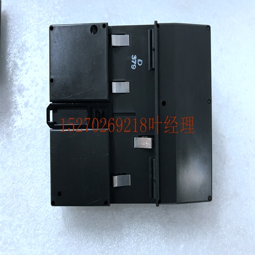
IS220PHRAH1B機器人卡件
出版物800T-PP010A-EN-P–2015年4月版權所有?2015,Inc.保留所有權利。美國印刷,LISTEN。思考。解決。和羅克韋爾軟件是股份有限公司的商標。商標不屬于其各自公司的財產。產品選擇觸點配置額定值目錄編號1-NO、1-NC A600 10A、600V 800TC-XAF觸點配置代碼1-NO、1-NC AF 2-NO、2-NC、非照明BF 2-NO、2-NC、照明G1F 3-NO、3-NC、非照亮HF 4-NO、4-NC、,無照明CF工廠配置設備產品描述目錄號類型4/13目錄號類型4/4X/13瞬時觸點無照明按鈕,黑色,1-NO,1-NC 800T-A2AF 800H-AR2AF瞬時觸點照明按鈕,綠色,無防護裝置的延長頭,通用LED,1-NO、1-NC 800T-QBH2GAF 800H-QRBH2GAF非發光觸發動作E-stop,標準45 mm紅色蘑菇頭,2-NO,2-NC 800T-TFXT6BF 800H-TFRXT6BF照明觸發動作緊急停止,標準大型紅色蘑菇頭、通用LED,2-NO、2-NC 800T-TFXJTQH2RG1F————三位無照明選擇開關,標準旋鈕,維護,標準凸輪,4-NO,4-NC 800T-J2CF 800H-JR2CF二位照明選擇開關、標準藍色旋鈕,維護,1-NO,1-NC 800T-2HBH2KB6OX 800H-2HRBH2KB6OX按壓測試指示燈,琥珀色,通用LED,1-NO,1-NC 800T-QTH2AAF 800H-QRTH2AAF示例目錄號配置安裝說明警告:為防止觸電,在安裝或維修前斷開電源。重要事項:800T設備應安裝在接地金屬外殼中,并正確粘接。將設備安裝在金屬外殼中時,在接觸塊和外殼的外露金屬部件之間保持1/2“(12.7)的最小間隙。800T設備的額定值為4型和13型,800H設備的額定為4、4X和13型。安裝在外殼的平坦光滑表面上。只有在正確安裝在具有相同額定值的外殼中時,設備才能保持其類型額定值。緊急停止按鈕僅安裝在非通風外殼中時,經UL NISD認證。公告800T/800H導向裝置(Cat 800T;800H)警告:對于額定為1級2類危險場所的照明和導向裝置,爆炸危險-除非電源已關閉或該區域已知無危險,否則不要更換燈泡。對于額定為1類2類危險場所的照明和指示燈裝置,必須將透鏡裝配到裝置上。額定為1類2類的設備在設備上有明確的標記。透鏡或蓋子必須緊貼襯套,以提供緊密密封。安裝(見圖1和圖2)1。從裝置上拆下以下零件:透鏡或蓋、安裝環、止推墊圈和圖例板或裝飾墊圈。2.根據圖1中的表格確定要使用的墊片的正確數量。3.將裝置從面板后部放入安裝孔。4.定位圖例板或裝飾墊圈,然后定位止推墊圈,止推墊圈柄腳與圖例板或飾墊圈和面板槽口接合。5.安裝安裝環并擰緊止推墊圈至25-30 lb in(2.8-3.4 Nm)。6.將透鏡或蓋子安裝到操作員身上。燈的更換:(卡口底座)1。拆下透鏡2。拆下燈:向內推燈,逆時針轉動,然后拆下3。安裝新燈:插入插座,向內推動并順時針轉動(見圖3)4。重新安裝鏡頭可用安裝附件:八角形安裝環用扳手-目錄號800T-N245用于800H指示燈安裝環的扳手-目錄編號800H-N10用于800T設備的設備連接套件,以滿足CSA標準C22.2第0.4號-目錄號800 T-N300(F)的連接要求注:括號中的尺寸以毫米為單位。9/16“(14.3)1/4”(6.4)直徑。鉆機(備用)首選安裝說明
Publication 800T-PP010A-EN-P – April 2015 Copyright ? 2015 , Inc. All Rights Reserved. Printed in USA. , LISTEN. THINK. SOLVE. and Rockwell Software are trademarks of , Inc. Trademarks not belonging to are property of their respective companies. Product Selection Contact Confi guration Rating Catalog Number 1-NO, 1-NC A600 10A, 600V 800TC-XAF Contact Confi guration Code 1-NO, 1-NC AF 2-NO, 2-NC, non-illuminated BF 2-NO, 2-NC, illuminated G1F 3-NO, 3-NC, non-illuminated HF 4-NO, 4-NC, non-illuminated CF Factory Confi gured Devices Product Description Catalog Number Type 4/13 Catalog Number Type 4/4X/13 Momentary contact non-illuminated push button, black, 1-NO, 1-NC 800T-A2AF 800H-AR2AF Momentary contact illuminated push button, green, extended head without guard, Universal LED, 1-NO, 1-NC 800T-QBH2GAF 800H-QRBH2GAF Non-iIluminated trigger action E-stop, standard 45 mm red mushroom head, 2-NO, 2-NC 800T-TFXT6BF 800H-TFRXT6BF Illuminated trigger action E-stop, standard jumbo red mushroom head, Universal LED, 2-NO, 2-NC 800T-TFXJTQH2RG1F - - - 3-position non-illuminated selector switch, standard knob, maintained, standard cam, 4-NO, 4-NC 800T-J2CF 800H-JR2CF 2-position illuminated selector switch, standard blue knob, maintained, Universal LED, 1-NO, 1-NC 800T-2HBH2KB6OX 800H-2HRBH2KB6OX Push-to-test pilot light, amber, Universal LED, 1-NO, 1-NC 800T-QTH2AAF 800H-QRTH2AAF Example Catalog Number Confi gurations Installation Instructions WARNING: To prevent electrical shock, disconnect from power source before installing or servicing. IMPORTANT: 800T devices should be mounted in and properly bonded to, a grounded metal enclosure. When installing the device in a metal enclosure, maintain 1/2” (12.7) minimum clearance between exposed metal parts of contact block and enclosure. 800T devices are rated Type 4 and 13, 800H devices are rated Type 4, 4X and 13. Install on a flat, smooth surface of an enclosure. Devices maintain their Type ratings only when properly mounted in an enclosure with the same rating(s). Emergency Stop Push Buttons are UL NISD Listed when mounted in a non-ventilated enclosure only. Bulletin 800T / 800H Pilot Devices (Cat 800T; 800H) WARNING: For those illuminated and pilot devices rated for Class 1 Division 2 Hazardous Locations, EXPLOSION HAZARD - Do not replace bulb unless power has been switched off or the area is known to be non-hazardous. For those illuminated and pilot light devices rated for Class 1 Division 2 Hazardous Locations, the lens must be assembled to the device. Those devices rated Class 1 Division 2 are marked specifically as such on the device. Lens or cap must be tight against bushing to provide a tight seal. Installation (see Figs. 1 and 2) 1. Remove the following parts from the unit: Lens or cap, mounting ring, thrust washer and legend plate or trim washer. 2. Determine the correct number of gaskets to be used per the table in Fig. 1. 3. Place the unit into the mounting hole from the rear of the panel. 4. Position legend plate or trim washer and then thrust washer, with thrust washer tang engaging legend plate or trim washer and panel notches. 5. Install mounting ring and tighten against thrust washer to 25 - 30 lb-in (2.8 - 3.4 Nm). 6. Install lens or cap to operator. Lamp Replacement: (Bayonet Base) 1. Remove Lens 2. To remove lamp: Push lamp inward, turn counterclockwise, and remove 3. To install new lamp: Insert in socket, push inward and turn clockwise (see Figure 3) 4. Reinstall Lens Available Mounting Accessories: Wrench for Octagonal Mounting Ring - Catalog No. 800T-N245 Wrench for 800H Pilot Light Mounting Ring - Catalog No. 800H-N10 Device Bonding Kit for 800T devices to meet the bonding requirements of CSA Standard C22.2 No. 0.4 - Catalog No. 800T-N300 (F) NOTE: Dimensions in parentheses are in millimeters. 9/16" (14.3) 1/4" (6.4) Dia. Drill (Alternate) Preferred Mounting Instructions


