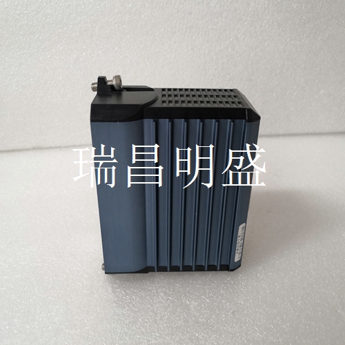
FOXBORO FBM232 P0926GW 自動(dòng)化模塊備件
注意:通過(guò)適當(dāng)?shù)慕拥鼗蚍至饕约笆褂渺o電控制包裝和材料搬運(yùn)產(chǎn)品,幫助保護(hù)控制器免受ESD的影響。通過(guò)接地、電離和使用導(dǎo)電和耗散靜電控制材料來(lái)耗散和中和。羅克韋爾自動(dòng)化出版物45MLA-IN002C-EN-P-2020年8月5 45MLA控制器安裝說(shuō)明?在示教過(guò)程中隨時(shí)關(guān)閉電源可取消該過(guò)程。先前存儲(chǔ)的值仍然有效。?模擬輸出在示教過(guò)程中處于激活狀態(tài),輸出值表示基于電流中斷光束和當(dāng)前示教過(guò)程期間示教值的實(shí)際狀態(tài)。?通過(guò)將DIP開(kāi)關(guān)1:8設(shè)置為ON并循環(huán)電源,可以重置默認(rèn)值(模擬輸出縮放到連接的燈陣列的全長(zhǎng))。?將不同長(zhǎng)度的光陣列對(duì)連接到控制器會(huì)導(dǎo)致模擬輸出縮放到陣列的整個(gè)長(zhǎng)度,從而覆蓋最小和最大模擬輸出值的任何設(shè)定值。?通過(guò)改變?cè)谑窘踢^(guò)程中呈現(xiàn)兩個(gè)不同大小對(duì)象的順序,可以使模擬輸出的斜率為正或負(fù)。例如,在步驟2中呈現(xiàn)較高的對(duì)象而在步驟3中呈現(xiàn)較短的對(duì)象會(huì)導(dǎo)致模擬輸出中的負(fù)斜率。功能描述-基本模型圖4-基本模型該控制器模型提供一個(gè)基本的離散(開(kāi)/關(guān))輸出,指示陣列的整體狀態(tài)。引腳列表表10顯示了主連接器J2上的引腳分配。S1 DIP開(kāi)關(guān)陣列上的DIP開(kāi)關(guān)設(shè)置DIP開(kāi)關(guān)1…6配置用于表11中所述的各種應(yīng)用。
TTENTION: Help protect the controller from ESD with proper grounding or shunting and the use of static control packaging and materials handling products. Dissipate and neutralize by grounding, ionization, and the use of conductive and dissipative static control materials. Rockwell Automation Publication 45MLA-IN002C-EN-P - August 2020 5 45MLA Controller Installation Instructions ? Turning off power at any time during the teach process cancels the process. The previously stored values remain valid. ? The analog output is active during the teach process and the output value represents the actual state based on the current interrupted beams and the values that are taught during the current teach process. ? Default values (analog output scaled to full length of connected light arrays) can be reset by setting DIP switch 1:8 to ON and cycling power. ? Connecting a different length light array pair to the controller results in the analog output being scaled to the full length of the array, thus overwriting any taught values for minimum and maximum analog output value. ? The slope of the analog output can be made positive or negative by changing the order in which the two different sized objects are presented during the teach process. For example, presenting the taller object in step 2 and the shorter object in step 3 results in a negative slope in the analog output. Functional Description — Basic Model Figure 4 - Basic Model This controller model provides a basic discrete (on/off) output that indicates the overall state of the arrays. Pin Listings Table 10 shows the allocation of pins on the main connector, J2. DIP Switch Settings DIP switches 1…6 on the S1 DIP switch array are configured for the various applications that are described in Table 11.


