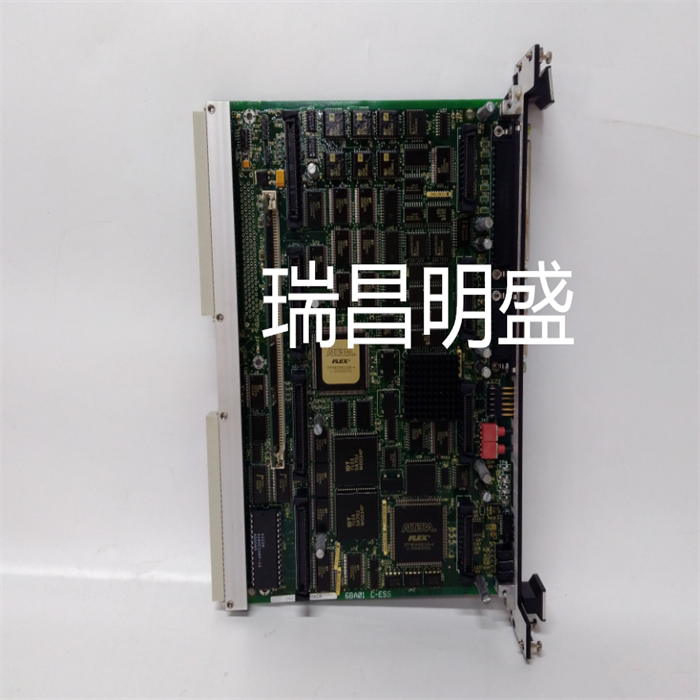
VMIVME-7807-412010工業備件
安裝負載共享模塊
設置和校準簡介在發電機組上安裝負載共享模塊后,使用此校準程序,以獲得負載共享期間所需的操作特性。1.檢查端子15、16、17和18上是否安裝了正確的跳線,以匹配電壓互感器二次電壓。參見工廠接線圖(圖1-3)。2.從負載分配線路端子10和11以及端子24和25處的SPM-A同步器(如果使用)上取下電線。3.通過短路端子13和14選擇同步操作。警告-啟動準備在啟動發動機、渦輪機或其他類型的原動機時緊急停機,以防止失控或超速,生命損失或財產損失。4.根據發動機制造商的說明啟動發動機。將發動機調整到額定轉速。對發電機組施加全負荷。注:最準確的校準是在滿載時進行的。但是,如果發電機組不能滿負荷運行,則應在低于滿負荷的情況下運行,并按比例降低本校準程序中給出的電壓讀數。
發電機組
以100 kW的功率運行一臺200 kW的發電機組,并將此校準程序中給出的所有電壓除以2。如果以這種方式減少負載,請確保在整個校準過程中以相同的量減少負載。5.順時針完全設置負載增益電位計。6.檢查端子22和23之間的負載信號電壓。調整負載增益電位計的6.0 Vdc信號。如果無法獲得該電壓,則將負載信號設置為盡可能接近6 Vdc。7.從發電機組上卸下負載。8.檢查端子22和23之間的電壓。該電壓應為0.0±0.25 Vdc。如果該電壓不正確,則說明負載分配模塊有故障或發電機上可能仍有負載。負載共享模塊手冊26011 12相位檢查警告-高電壓開路CT(電流互感器)兩端的高電壓可能導致死亡或嚴重傷害。
Installing the Load Sharing Module
Setup and Calibration IntroductionAfter installing the load sharing module on the generator set, use this calibration procedure to obtain the required operating characteristics during load sharing. 1. Check whether correct jumpers are installed on terminals 15, 16, 17 and 18 to match the secondary voltage of voltage transformer. Refer to the factory wiring diagram (Figure 1-3). 2. Remove the wires from the SPM-A synchronizer (if used) at terminals 10 and 11 of the load sharing line and terminals 24 and 25. 3. Select synchronous operation through short-circuit terminals 13 and 14. WARNING - STARTING PREPARATION Emergency shutdown when starting the engine, turbine, or other type of prime mover to prevent runaway or overspeed, loss of life, or property damage. 4. Start the engine according to the engine manufacturer's instructions. Adjust the engine to the rated speed. Apply full load to the generator set. Note: The most accurate calibration is performed at full load. However, if the generator set cannot be operated at full load, it should be operated below full load and the voltage readings given in this calibration procedure should be reduced proportionally.
Generator Set
Run a 200 kW generator set at 100 kW and divide all the voltages given in this calibration procedure by 2. If the load is reduced in this way, ensure that the load is reduced by the same amount throughout the calibration process. 5. Fully set the load gain potentiometer clockwise. 6. Check the load signal voltage between terminals 22 and 23. Adjust the 6.0 Vdc signal of the load gain potentiometer. If this voltage is not available, set the load signal as close to 6 Vdc as possible. 7. Remove the load from the generator set. 8. Check the voltage between terminals 22 and 23. The voltage should be 0.0 ± 0.25 Vdc. If the voltage is incorrect, the load distribution module is faulty or there may still be a load on the generator. Load Sharing Module Manual 26,011 12 Phase Check Warning - High Voltage Open Circuit CT (Current Transformer) High voltage at both ends may cause death or serious injury.


