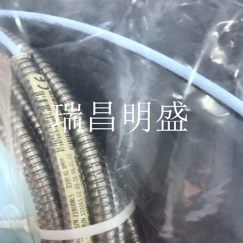
330161-02-85-05-94-01-02輸入輸出模塊
接線歐式連接器
要將接線板從底座上拆下,請松開將接線板固定到底座上的螺釘,然后牢牢抓住接線板并拉動。不要用導線將塊拉出,因為這可能會松開或損壞導線或連接器。典型輸入/輸出模塊參考3301現(xiàn)場接線圖包了解推薦接線。此外,不要從導線上去除超過6毫米(0.25英寸)的絕緣層。3301/20操作和維護4 I/O模塊說明25 4.1.4電纜引腳輸出電纜編號02290860主機(或機架接口模塊)至外部調(diào)制解調(diào)器電纜編號130118--主機至3301機架RS-232接口電纜4 I/O模塊描述3301/20運行和維護26電纜編號132632--主計算機至3301機架電纜RS-422 PVC電纜編號132633--主機至3301機架電纜RS-422 Teflon 3301/20操作和維護4 I/O模塊說明27電纜編號130119-01主機至RS-232/422轉(zhuǎn)換器電纜編號130120-- RS-232/42轉(zhuǎn)換器至3301機架線纜(RS-422)-PVC絕緣4 I/O模塊描述3301/20操作和維護28電纜編號130121-- RS-422延長電纜電纜編號130122-- RS-422 3301機架至3301機架電纜-PVC絕緣3301/20操作和維護4 I/O模塊說明29電纜編號131106-- RS-232/422轉(zhuǎn)換器至3301機架線纜(RS-422)-特氟龍絕緣電纜編號131107--RS-422 350機架至3301架架電纜-特氟隆絕緣4 I/O模塊描述3301/20運行和維護30 4.2數(shù)據(jù)管理器I/O模塊Data Manager I/O模塊必須安裝在電源輸入模塊和機架接口I/O模塊之間的電源后面(在機架安裝或面板安裝機架中)或電源輸入模塊與機架接口I/O模件之間的電源上面(在隔板機架中)。數(shù)據(jù)管理器I/O模塊的功能是將3301機架連接到TDI或DDI通信處理器。每個端口最多可連接24個通道,從3301機架到通信處理器。有關(guān)可用的不同選項,請參閱第10頁的表格。1) 用于將靜態(tài)信息從3301機架的端口1傳輸至通信處理器上的靜態(tài)連接器。2) 用于將動態(tài)信息從3301機架的端口1傳輸至通信處理器上的動態(tài)連接器。3) 用于將信息從3301機架的端口2傳輸至通信處理器上的靜態(tài)連接器。4) 用于將動態(tài)信息從3301機架的端口2傳輸至通信處理器上的動態(tài)連接器。
注:3301監(jiān)測系統(tǒng)支持DDI和TDI通信處理器。
注:如果拆除機架接口模塊,數(shù)據(jù)管理器I/O將停止運行。3301/20操作和維護4輸入/輸出模塊說明31 4.2.1電纜引腳輸出電纜編號129386-01 3301靜態(tài)至TDI電纜電纜編號12937-01 3301靜態(tài)至DDI電纜4輸入/輸入模塊說明3301/20運行和維護32電纜編號02290160動態(tài)數(shù)據(jù)電纜DDI/TDI 3301/40操作和維護5維護33 5維護本節(jié)說明如何驗證機架接口模塊和I/O模塊工作正常。正確執(zhí)行時,可在機架通電時將該模塊安裝到機架中或從機架中卸下。有關(guān)正確程序,請參閱機架安裝和維護手冊(零件號129766-01)。5.1 RIM主機端口測試實用程序使用RIM主機接口測試實用程序驗證機架接口模塊和機架接口輸入/輸出模塊上的主機端口是否正常工作。在運行RIM主機端口測試實用程序之前,將電纜130118--(主機至3301機架RS-232接口電纜)連接在機架接口模塊前面的配置端口連接器或機架接口I/O模塊上的主機連接器與安裝了該實用程序的計算機之間。有關(guān)該實用程序的詳細信息,請參閱3301監(jiān)測系統(tǒng)機架配置和實用程序指南和機架配置軟件。5.2執(zhí)行固件升級有時可能需要更換3301/20機架接口模塊(RIM)附帶的原始固件。以下說明描述了如何刪除現(xiàn)有固件并將其替換為升級固件。固件升級后,RIM需要使用3301機架配置軟件重新配置。執(zhí)行RIM固件升級需要以下項目:大型平頭螺絲刀。接地腕帶*小型平頭螺絲刀升級固件IC。**有關(guān)零件號,請參閱第7節(jié)(訂購信息)。用戶可以使用自己的接地腕帶。5.2.1安裝程序完成以下步驟
Wiring European connector
To remove the terminal block from the base, loosen the screw that secures the terminal block to the base, then firmly grasp the terminal block and pull. Do not pull the block out with wires as this may loosen or damage the wires or connectors. Refer to the 3301 Field Wiring Diagram Package for typical I/O modules for recommended wiring. Also, do not remove more than 6 mm (0.25 in) of insulation from the wire. 3301/20 Operation and Maintenance 4 I/O Module Description 25 4.1.4 Cable Pin Output Cable Number 02290860 Host (or Rack Interface Module) Cable number to external modem 130118 -- Host computer to 3301 rack RS-232 interface cable 4 I/O module description 3301/20 operation and maintenance 26 Cable number 132632 -- Host computer to 3301 rack cable RS-422 PVC cable number 132633 -- Host computer to 3301 rack cable RS-422 Teflon 3301/20 operation and maintenance 4 I/O module description 27 Cable number 130119-01 Host computer to RS-232/422 converter cable number 130120 -- RS-232/42 converter to 3301 rack cable (RS-422) -PVC insulated 4 I/O module description 3301/20 Operation and maintenance 28 Cable number 130121 -- RS-422 extension cable number 130122 -- RS-422 3301 rack to 3301 rack cable PVC insulated 3301/20 Operation and maintenance 4 I/O module description 29 Cable number 131106 -- RS-232/422 converter to 3301 rack cable (RS-422) -Teflon insulated cable No. 131107 -- RS-422 350 rack to 3301 rack cable - Teflon insulated 4 I/O module description 3301/20 Operation and maintenance 30 4.2 Data manager I/O module Data Manager I/O module must be installed behind the power supply between the power input module and the rack interface I/O module (in a rack mounted or panel mounted rack) or above the power supply between the power input module and the rack interface I/O module (in a bulkhead rack). The function of the data manager I/O module is to connect the 3301 rack to the TDI or DDI communication processor. Each port can connect up to 24 channels, from the 3301 rack to the communication processor. See the table on page 10 for the different options available. 1) Used to transfer static information from port 1 of the 3301 rack to the static connector on the communication processor. 2) Used to transmit dynamic information from port 1 of the 3301 rack to the dynamic connector on the communication processor. 3) Used to transfer information from port 2 of the 3301 rack to a static connector on the communication processor. 4) Used to transmit dynamic information from port 2 of the 3301 rack to the dynamic connector on the communication processor.
Note: 3301 monitoring system supports DDI and TDI communication processors.
Note: If you remove the Rack Interface Module, the Data Manager I/O will stop. 3301/20 Operation and maintenance 4 I/O module description 31 4.2.1 Cable pin output cable number 129,386-01 3301 Static to TDI cable cable number 12,937-01 3301 Static to DDI cable 4 I/O module description 3301/20 Operation and maintenance 32 Cable number 02,290,160 Dynamic data cable DDI/TDI 3301/40 Operation and maintenance 5 Maintenance 33 5 Maintenance This section describes how to verify that the Rack Interface Module and I/O Module are working properly. When performed correctly, the module can be installed in or removed from the rack when the rack is powered up. Refer to the Rack Installation and Maintenance Manual (part number 129766-01) for the correct procedure. 5.1 RIM Host Port Test Utility Use the RIM Host Interface Test Utility to verify that the host ports on the Rack Interface Module and the Rack Interface I/O Module are working properly. Before running the RIM host port test utility, connect cable 130118 -- (host to 3301 rack RS-232 interface cable) between the configuration port connector on the front of the Rack Interface Module or the host connector on the Rack Interface I/O Module and the computer where the utility is installed. For more information about this utility, refer to the 3301 Monitoring System Rack Configuration and Utilities Guide and Rack Configuration Software. 5.2 Performing a firmware upgrade may sometimes require replacing the original firmware that came with the 3301/20 Rack Interface Module (RIM). The following instructions describe how to delete existing firmware and replace it with upgraded firmware. After the firmware upgrade, RIM needs to be reconfigured using the 3301 Rack Configuration Software. The following items are required to perform the RIM firmware upgrade: large flat screwdriver. Grounding wrist strap * small flat screwdriver to upgrade firmware IC** Refer to Section 7 (Ordering Information) for part numbers. Users can use their own grounding wrist strap. 5.2.1 The installation procedure completes the following steps


