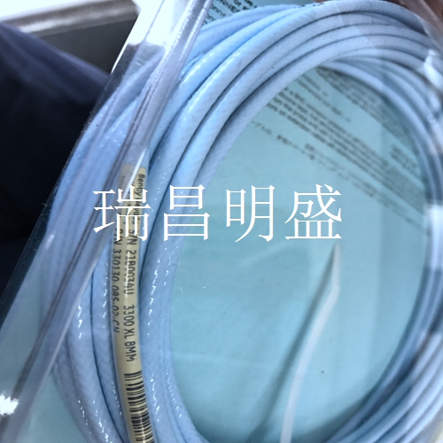
330130-085-02-05延伸線纜
機架報警抑制
(INHB)用于防止在3500機架中的任何監(jiān)視器或繼電器上宣布報警。這通常用于執(zhí)行維護功能。機架復位(RST)用于在3500機架中的模塊要復位時發(fā)出信號。該觸點的功能與機架接口模塊前面板上的機架復位開關相同。4.1.1將機架接口I/O模塊連接到主機3500機架可使用兩種類型的機架接口輸入/輸出模塊,可通過多種方式將主機連接到機架。RS-232/RS-422主機連接器使用RS-232、RS-422(帶轉換器)或外部調制解調器連接到主機。還用于僅使用RS-422連接到菊花鏈中的前一個機架。使用RS-232/RS-422開關選擇主機連接器使用RS-232還是RS-422協(xié)議。內部調制解調器連接器使用RJ11兼容的模塊化插頭連接到主機,以連接到電話系統(tǒng)。3500/20操作和維護4 I/O模塊說明19 4.1.1.1通過RS232將機架接口I/O模塊連接到主機。通信速率受3500主機和第一個機架接口模塊之間選擇的波特率限制。連接至3500主機的機架接口輸入/輸出模塊上的開關必須位于RS232位置。1) 主機2)電纜130118-XXX-XX有各種長度,最長可達30米(100英尺)。有關上述電纜的具體選項,請參閱第7節(jié)。4 I/O模塊說明3500/20操作和維護20 4.1.1.2通過RS422將機架接口I/O模塊連接到主機。通信速率受3500主機和第一個機架接口模塊之間選擇的波特率限制。連接至3500主機的機架接口輸入/輸出模塊上的開關必須位于RS-422位置。對于150米(500英尺)或以下的長度,使用電纜130120-XXXX-XX(PVC絕緣)或電纜131106-XXXX-X(特氟龍絕緣)。對于長度大于150米(500英尺)的電纜,使用一根電纜130120-XXXX-XX(PVC絕緣)或電纜131106-XXXX-X(特氟龍絕緣)以及盡可能多的RS-422延長電纜130121-XX-XX(150米(500ft)標準長度),以創(chuàng)建最大1220米(4000英尺)的線纜。
轉換器
用于110 Vac的RS-232/RS-422轉換器使用零件號02230411。用于220 Vac的零件號02230 412。電纜130119-01的長度為3米(10英尺)。有關上述電纜的具體選項,請參閱第7節(jié)。3500/20操作和維護4 I/O模塊說明21 4.1.1.3通過外部調制解調器將機架接口I/O模塊連接到主機。通信速率受3500主機和第一個機架接口輸入/輸出模塊之間選擇的波特率限制。連接到調制解調器的機架接口I/O模塊上的開關必須處于RS-232位置。1) 電纜02290860有3米(10英尺)長。有關上述電纜的具體選項,請參閱第7節(jié)。4 I/O模塊說明3500/20操作和維護22 4.1.1.4通過內部調制解調器將機架接口I/O模塊連接到主機。通信速率受主機和第一個機架接口輸入/輸出模塊之間選擇的波特率限制。1) 電纜02290860有3米(10英尺)長。2) 電話線請參閱第7節(jié),了解上述電纜的具體選項。3500/20操作和維護4 I/O模塊說明23 4.1.2菊花鏈機架接口I/O模塊本節(jié)介紹如何將機架接口I/O模件菊花鏈在一起。至主機(見第4.1.1節(jié))。菊花鏈機架接口I/O模塊時,請注意以下事項:?使用主機端口連接到主機或菊花鏈中靠近主機的機架。?使用機架RS-422端口連接到離主機更遠的機架。?使用以下電纜連接菊花鏈中的機架:-對于150米(500英尺)或以下的長度,使用電纜130122-XXXX-XX(PVC絕緣)或電纜131107-XXXX-X(特氟隆絕緣)。-對于長度大于150米(500英尺)的電纜,使用一根電纜130122-XXXX(PVC絕緣)或電纜131107-XXXX-XX(特氟龍絕緣)以及盡可能多的RS-422延長電纜130121-XXX-XX(150米(500ft)標準長度),以創(chuàng)建長度達1220米(4000ft)的電纜。有關上述電纜的具體選項,請參閱第7節(jié)。
Rack Alarm Inhibit
(INHB) is used to prevent alarms from being declared on any monitor or relay in the 3500 rack. This is typically used to perform maintenance functions. Rack Reset (RST) is used to signal when a module in a 3500 rack is to be reset. This contact has the same function as the Rack Reset switch on the front panel of the Rack Interface Module. 4.1.1 There are two types of Rack Interface I/O Modules that can be used to connect a Rack Interface I/O Module to a host 3500 rack. The host can be connected to the rack in many ways. The RS-232/RS-422 host connector connects to the host using RS-232, RS-422 (with converter), or an external modem. It is also used to connect to the previous rack in the daisy chain using only RS-422. Use the RS-232/RS-422 switch to select whether the host connector uses the RS-232 or RS-422 protocol. The internal modem connector uses RJ11 compatible modular plugs to connect to the host computer for connection to the telephone system. 3500/20 Operation and Maintenance 4 I/O Module Description 19 4.1.1.1 Connect the Rack Interface I/O Module to the Host Computer via RS232. The communication rate is limited by the baud rate selected between the 3500 host computer and the first Rack Interface Module. The switch on the Rack Interface I/O Module that is connected to the 3500 host computer must be in the RS232 position. 1) Host 2) Cable 130118-XXX-XX has various lengths, up to 30 meters (100 feet). Refer to Section 7 for specific options for these cables. 4 I/O Module Description 3500/20 Operation and Maintenance 20 4.1.1.2 Connect the Rack Interface I/O Module to the host through RS422. The communication rate is limited by the baud rate selected between the 3500 host computer and the first Rack Interface Module. The switch on the Rack Interface I/O Module that is connected to the 3500 host computer must be in the RS-422 position. For lengths of 150 meters (500 feet) or less, use cable 130120-XXXX-XX (PVC insulated) or cable 131106-XXXX-X (Teflon insulated). For cables longer than 150 meters (500 feet), use one cable 130120-XXXX-XX (PVC insulated) or cable 131106-XXXX-X (Teflon insulated) and as many RS-422 extension cables 130121-XX-XX (150 meters (500 feet) standard length) as possible to create a maximum of 1220 meters (4000 feet).
converter
The RS-232/RS-422 converter for 110 Vac uses part number 02230411. Part number 02230 412 for 220 Vac. The length of cable 130119-01 is 3 meters (10 feet). Refer to Section 7 for specific options for these cables. 3500/20 Operation and Maintenance 4 I/O Module Description 21 4.1.1.3 Connect the Rack Interface I/O Module to the host computer through an external modem. The communication rate is limited by the baud rate selected between the 3500 host computer and the first Rack Interface I/O Module. The switch on the Rack Interface I/O Module connected to the modem must be in the RS-232 position. 1) The cable 02290860 is 3 meters (10 feet) long. Refer to Section 7 for specific options for these cables. 4 I/O Module Description 3500/20 Operation and Maintenance 22 4.1.1.4 Connect the Rack Interface I/O Module to the host computer through an internal modem. The communication rate is limited by the baud rate selected between the host and the first Rack Interface I/O Module. 1) The cable 02290860 is 3 meters (10 feet) long. 2) Refer to Section 7 for telephone lines for specific options for the above cables. 3500/20 Operation and Maintenance 4 I/O Module Description23 4.1.2 Daisy Chain Rack Interface I/O Module This section describes how to daisy chain rack interface I/O modules together. To the main engine (see section 4.1.1). When daisy chain rack interface I/O modules, please note the following: ? Use the host port to connect to the host or the rack near the host in the daisy chain. ? Use the rack RS-422 port to connect to a rack farther from the host. ? Use the following cables to connect the racks in the daisy chain: - For lengths of 150 meters (500 feet) or less, use cable 130122-XXXX-XX (PVC insulated) or cable 131107-XXXX-X (Teflon insulated)- For cables longer than 150 meters (500 feet), use one cable 130122-XXXX (PVC insulated) or cable 131107-XXXX-XX (Teflon insulated) and as many RS-422 extension cables 130121-XXX-XX (150 meters (500 feet) standard length) as possible to create cables up to 1220 meters (4000 feet) long. Refer to Section 7 for specific options for these cables.


