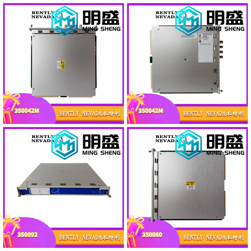
19047-01震動檢測器
內置以太網
配置用戶通過使用筆記本電腦或PC上運行的軟件創建配置文件并通過內置以太網連接將文件下載到監視器,來定義監視器操作和Modbus網關寄存器映射。1900/65A將配置信息永久存儲在非易失性存儲器中,并可將此信息上傳至PC進行更改。顯示模塊1900/65A支持可選的顯示器/鍵盤,以查看頻道信息或進行細微的配置更改。這使得1900/65A可以作為獨立的組件運行。如果需要,用戶可以將顯示器安裝在距離監視器模塊75米(250英尺)的地方。1900/65A通用設備監測器數據表2/22 173401 Rev.T規范輸入傳感器輸入用戶可以配置通道1至通道4以接受加速度、速度或位移傳感器的輸入。傳感器通道類型通道類型定義了將應用于輸入信號的處理功能以及將從該輸入導出的變量或測量值的類型。通道類型還定義必須使用的傳感器類型。傳感器通道類型包括:l加速度或往復加速度l速度或往復速度l徑向振動(軸振動)l推力(軸軸向位移)l位置l速度加速度和往復加速度通道類型加速度通道類型和往復加速通道類型支持兩線和三線加速度傳感器。往復加速度通道類型已禁用定時OK通道失效。
加速度變量
往復加速度變量加速度變量和往返加速度變量是從原始傳感器信號中過濾和處理的測量值。加速度通道類型和往復加速度通道類型連續處理每個通道最多四個變量。振動最多三次帶通濾波振幅測量。加速度包絡用戶可以將加速度包絡算法應用于一個加速度或往復加速度變量。偏置電壓用戶可以將傳感器偏置電壓的值分配給任何變量。配置選項每個變量都通過以下選項獨立配置。振動變量l峰值或RMS l公制或英制單位l濾波器角頻率l滿量程l加速度積分到速度包絡變量l濾波器角頻l標準或增強型解調濾波器振動變量0.5 Hz–25 kHz可配置4極高通、4極低通包絡高通25 Hz至5 kHz,可配置4極包絡低通125 Hz至25 kHz,可配置2極包絡可變高通0.1 Hz min。,但大于包絡可變低通2極包絡可變低通大于包絡變量高通且小于包絡高通4極偏置濾波器0.01 Hz 1極低通OK濾波器2.4 kHz 1極低通滿量程振動20至500 m/s2(2至50 g)峰值
Built in Ethernet
The configuration user defines the monitor operation and Modbus gateway register mapping by using the software running on the laptop or PC to create a configuration file and downloading the file to the monitor through the built-in Ethernet connection. 1900/65A permanently stores the configuration information in non-volatile memory, and can upload this information to the PC for change. The display module 1900/65A supports an optional display/keyboard to view channel information or make minor configuration changes. This allows the 1900/65A to operate as a standalone component. If necessary, the user can install the monitor 75 meters (250 feet) from the monitor module. 1900/65A Universal Unit Monitor Data Sheet 2/22 173401 Rev. T Specification Input Transducer Inputs Users can configure channels 1 through 4 to accept input from acceleration, velocity, or displacement transducers. Sensor Channel TypeChannel Type defines the processing functions that will be applied to the input signal and the types of variables or measurements that will be derived from that input. The channel type also defines the type of sensor that must be used. The sensor channel types include: l acceleration or reciprocating acceleration l velocity or reciprocating velocity l radial vibration (shaft vibration) l thrust (shaft axial displacement) l position l velocity acceleration and reciprocating acceleration channel type acceleration channel type and reciprocating acceleration channel type. Two wire and three wire acceleration sensors are supported. Reciprocating acceleration channel type has disabled timed OK channel failure.
Acceleration variable
Reciprocating acceleration variable acceleration variable and reciprocating acceleration variable are measured values filtered and processed from the original sensor signal. The Acceleration Channel Type and Reciprocating Acceleration Channel Type continuously process up to four variables per channel. Vibration up to three band-pass filtered amplitude measurements. Acceleration Envelope Users can apply the acceleration envelope algorithm to an acceleration or reciprocating acceleration variable. Offset Voltage The user can assign the value of the sensor offset voltage to any variable. Each variable of the configuration options is independently configured through the following options. Vibration variable l peak value or RMS l metric or imperial unit l filter angular frequency l full scale l acceleration integration to velocity envelope variable l filter angular frequency l standard or enhanced demodulation filter vibration variable 0.5 Hz – 25 kHz can be configured with 4-pole high pass, 4-pole low pass envelope high pass 25 Hz to 5 kHz, 4-pole envelope low pass 125 Hz to 25 kHz, and 2-pole envelope variable high pass 0.1 Hz min., But it is larger than envelope variable low pass 2-pole envelope variable low pass larger than envelope variable high pass and smaller than envelope high pass 4-pole offset filter 0.01 Hz 1-pole low pass OK filter 2.4 kHz 1-pole low pass full range vibration 20 to 500 m/s2 (2 to 50 g) peak


