


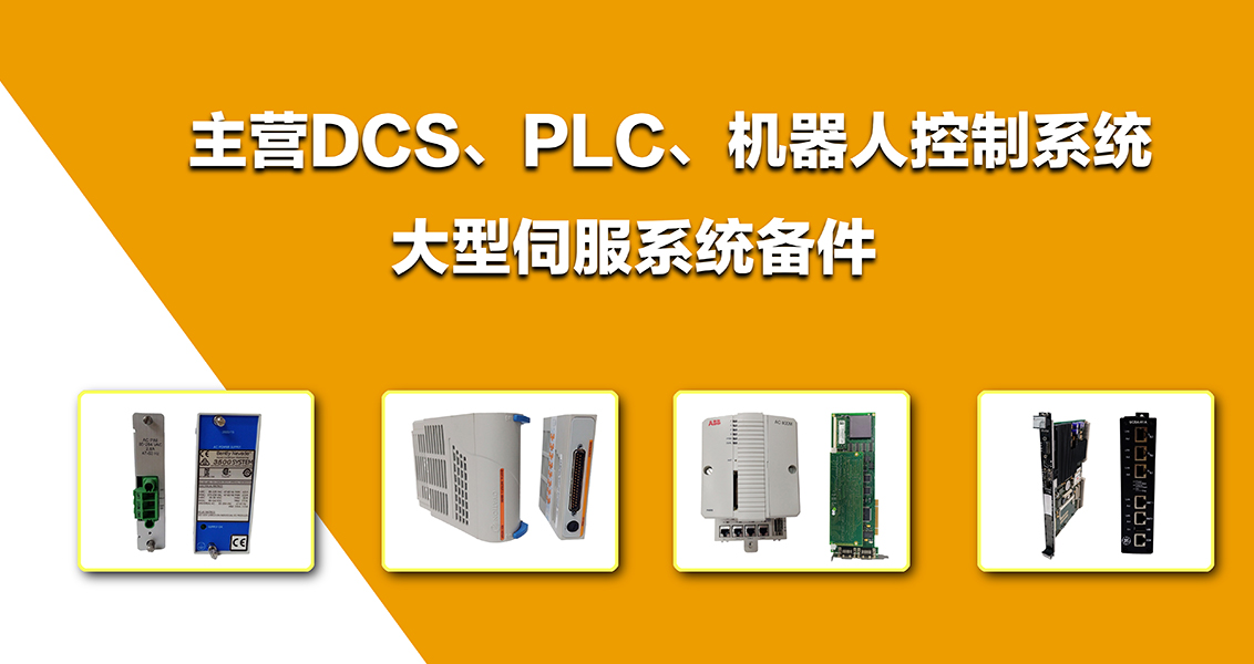

公司主營產品圖展示
")
產品優勢
1:國外專業的供貨渠道,具有價格優勢
2:產品質量保證,讓您售后無憂
3:全國快遞包郵
4:一對一服務
產品詳情介紹
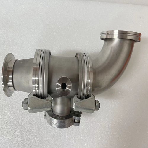
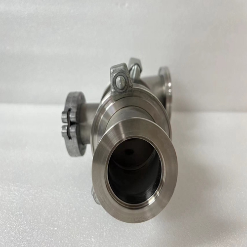
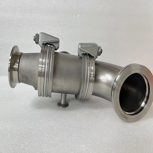
BALZERS IKR020底座
阻止復制時間,復制時間輸入信號或輸出
來自/到傳輸的信號記憶力
它包括:–凈拷貝時間0.2毫秒
–2個接口中斷每個0.1毫秒–如果由遠程模塊擴展,則等待訪問時間
授權:二進制模塊。僅:1.1毫秒,也是模擬模塊:2.7毫秒
(開啟2倍詢問時間CS31系統總線)該等式假設處理器總是在最不利的時刻進入。
循環時間tC存儲在KD 00,00中,可以是以5毫秒時間步長選擇。如果所選循環時間為太短,處理器將無法完成任務分配給它。屆時它將默認。如果這種時間不足在幾個周期內變得過大,處理器將中止程序執行和輸出錯誤(FK2)。使用一些功能塊,例如PID控制器,無錯誤執行取決于精確的定時序列確保有更大的時間儲備。循環時間的正確設置可以通過以下方式進行檢查以下程序:–將用戶程序加載到中央單元。
–如果操作模式已從單機到總線主機:電源打開或菜單項編程軟件中的“啟用PLC模式”。
–使用菜單查詢容量利用率“顯示PLC狀態”項。
–更改周期時間tC,直到容量利用率低于80%。
總線主中央單元+1二進制輸入模塊+1二進制輸出模塊
+2個模擬輸入模塊不考慮地址范圍,以下模塊可以連接到CS31系統總線:
–最多1個總線主機
–最多31個遠程模塊/從機中央單元07 KR 91/07 KT 92/93的地址范圍造成了進一步的限制:
–最多12個模擬輸入模塊
–最多12個模擬輸出模塊
–最多31個二進制輸入模塊
–最多31個二進制輸出模塊
根據安裝結構和遙控器類型,可能會有進一步的限制模塊。有關建議的地址,請參閱第A2.2章。
Block copy time, time for copying
the input signals or the out-put
signals from/to the transfer
memory.
It includes:
– Net copy time 0.2 ms
– 2 interface interrupts of
0.1 ms each
– If expanded by remote modules, waiting time for access
authorization:
binary mod. only: 1.1 ms,
also analog mod.: 2.7 ms
(2 x interrogation time on
the CS31 system bus)This equation assumes that the processor always gets
access in the most unfavourable moment.
The cycle time tC is stored in KD 00,00 and can be
selected in 5 ms time steps. If the selected cycle time is
too short, the processor will not be able to fulfill the tasks
assigned to it. It will come in default then.If this lack of time is getting too large over several cycles,
the processor will abort the program execution and output
an error (FK2).
Using some function blocks, such as the PID controller,
the error-free execution depends on an exact timing
sequence. Make sure that there is a larger time reserve.
The correct setting of the cycle time can be checked by
the following procedure:
– Loading the user program into the central unit.
– If the operating mode has been switched over from
stand-alone to bus master: Power ON or menu item
”Enable PLC mode” in the programming software.
– Interrogation of the capacity utilization using the menu
item of ”Display PLC status”.
– Changing the cycle time tC until the capacity utilization
is below 80 %.
Example: Bus master central unit + 1 binary input
module + 1 binary output module
+ 2 analog input modules Without regard to the address ranges, the following modules can be connected to a CS31 system bus:
– max. 1 bus master
– max. 31 remote modules / slaves
Further restrictions result from the address range of the central units 07 KR 91 / 07 KT 92/93:
– max. 12 analog input modules
– max. 12 analog output modules
– max. 31 binary input modules
– max. 31 binary output modules
There may be further restrictions according to the structure of the installation and the type of remote
modules. For the recommended addresses, see chapter A2.2.