


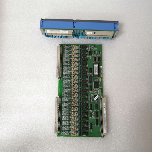
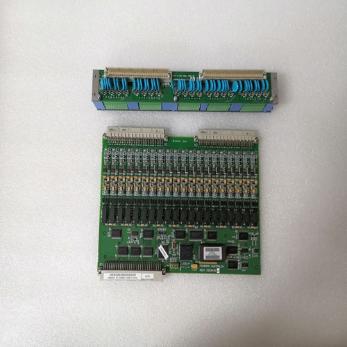
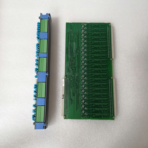
公司主營(yíng)產(chǎn)品圖展示
")
產(chǎn)品優(yōu)勢(shì)
1:國(guó)外專(zhuān)業(yè)的供貨渠道,具有價(jià)格優(yōu)勢(shì)
2:產(chǎn)品質(zhì)量保證,讓您售后無(wú)憂(yōu)
3:全國(guó)快遞包郵
4:一對(duì)一服務(wù)
產(chǎn)品詳情介紹
FOXBORO 0303440C+0303458A工控卡件
模塊有一個(gè)內(nèi)部參考接頭。這個(gè)將此結(jié)的溫度值添加到熱電偶測(cè)量的溫度。分辨率12位+符號(hào)(1 LSB=0.4°C)評(píng)估誤差在0…+1600°C+/-滿(mǎn)量程的0.5%范圍內(nèi)(線性、線性化、溫度范圍,分辨率,調(diào)整)電纜長(zhǎng)度,如果電纜平行敷設(shè)屏蔽最大50 m雙芯屏蔽,橫截面>0.5 mm2,最大200 m未使用的通道必須短路連接至ABB Procontic CS31系統(tǒng)總線接口標(biāo)準(zhǔn)EIA RS–485電氣隔離與電源電壓和輸入-裝置在通電后自動(dòng)初始化。-初始化后,錯(cuò)誤指示燈熄滅。模擬輸入I0的值顯示在6個(gè)led上右側(cè),led的?+5 V?和?±15 V?照亮。● 選擇電流或電壓電流或電壓輸入之間的選擇取決于在插入式底座上的接線上。當(dāng)裝置為配置為4…20 mA,顯示可用范圍在下表中。必須配置模擬輸出因?yàn)槌鰪S默認(rèn)設(shè)置為±10 V。
裝置在通電后自行初始化
初始化后,錯(cuò)誤指示燈熄滅。的值模擬輸出00顯示在右側(cè)的8個(gè)led上led的?+5V?和?±15V?點(diǎn)亮。對(duì)于UCZA/UCZB,地址08…14只允許與SCZ單元一起使用。對(duì)于PC板07 CM 90和耦合器板07 CS 61或35 CS 91,請(qǐng)參閱其各自的說(shuō)明。● 具體配置:ICSM 06 A6作為二進(jìn)制遠(yuǎn)程單元ICSM 06 A6遠(yuǎn)程裝置可用作二進(jìn)制CS31總線上的遠(yuǎn)程單元。此特定配置允許連接31CS31總線上的模擬遠(yuǎn)程單元,而不是12。這意味著可以發(fā)送或接收所有模擬值由中央單元作為二進(jìn)制值。模擬/二進(jìn)制和二進(jìn)制/模擬轉(zhuǎn)換是由遠(yuǎn)程單元實(shí)現(xiàn)。二進(jìn)制配置的設(shè)置使用雙列直插式開(kāi)關(guān)插件底座的2和3位于on位置。在這種情況下(二進(jìn)制配置),只有偶數(shù)地址允許,遠(yuǎn)程單元的實(shí)際地址為由物理地址乘以2得到。對(duì)于PC板07 CM 90和耦合器板07 CS 61和35 CS 91,請(qǐng)參閱其各自的說(shuō)明。注:此特定配置允許在帶有07 CS 61耦合器的CS31總線上使用大量遠(yuǎn)程單元。
ICSM 06 A6僅使用64個(gè)I/O點(diǎn)(而不是128個(gè))。T200配置表的代碼為EA32。中央單元必須在模擬配置中設(shè)置模式4-20 mA,然后移動(dòng)開(kāi)關(guān)2和3處于ON位置。在模式4-20 mA下,不可能檢測(cè)到開(kāi)路。該值始終為0,從不為負(fù)。
The module has an internal reference junction. The
temperature value of this junction is added to the
temperature measured by the thermocouple.
Resolution 12 bits + sign (1 LSB = 0.4°C)
Evaluation error within the range of 0...+1600°C +/– 0.5 % of full scale
(linearity, linearization, temperature range,
resolution, adjustment)
Cable length, if cables have been laid in parallel
shielded max. 50 m
two-core shielded and cross section > 0.5 mm2 max. 200 m
Unused channels have to be short–circuited
Connection to the ABB Procontic CS31 system bus
Interface standard EIA RS–485
Electrical isolation versus supply voltage and inputs - The unit initializes itself after power ON.
- The error led goes out after initialization.
The value of the analog input I0 is displayed on the 6 led’s
on the right and the led’s ?+ 5 V? and ?± 15 V? are
illuminated.● Selection current or voltage
The selection between current or voltage input is dependent
upon the wiring on the plug-in base. When the unit is
configured for 4 … 20 mA, the ranges available are shown
in the table below. The analog outputs must be configured
as the factory default setting is ± 10 V.The unit initializes itself after power on.
The error led goes out after initialization. The value of the
analog output 00 is displayed on the 8 led's on the right
and the led's ?+ 5V? and ?± 15V? are illuminated.In the case of UCZA/UCZB, the addresses 08 … 14 are only allowed with the SCZ unit.
For the PC board 07 CM 90 and the coupler boards 07 CS 61 or 35 CS 91, refer to their own description.
● Specific configuration : ICSM 06 A6 as binary remote
unit
The ICSM 06 A6 remote unit can be used as a binary
remote unit on the CS31 bus.
This specific configuration allows the connection of 31
analog remote units on CS31 bus instead of 12.
That means that all analog values can be sent or received
by the central unit as binary values.
The analog/binary and binary/analog conversions are
realized by the remote unit.
The setting of binary configuration is with the dip switches
2 and 3 of the plug-in base on ON position.
In this case (binary configuration), only the even addresses
are allowed and the real address of the remote unit is
obtained by the physical address multiplied by 2.
For the PC board 07 CM 90 and the coupler boards 07 CS 61 and 35 CS 91, refer to their own description.
Note : This specific configuration allows a high number of remote units on CS31 bus with the 07 CS 61 coupler.
The ICSM 06 A6 uses only 64 I/O points (instead of 128). The code for T200 configuration table is EA32.
The mode 4 - 20 mA has to be set in analog configuration by the central unit then, the switches 2 and 3 are moved
in ON position.
In mode 4 - 20 mA, it is not possible to detect on opened circuit. The value is always 0 and never negative.