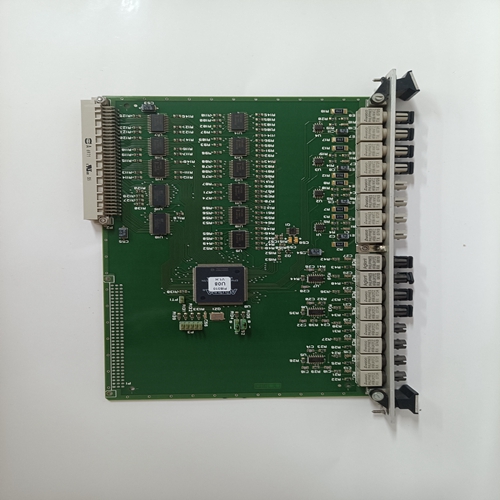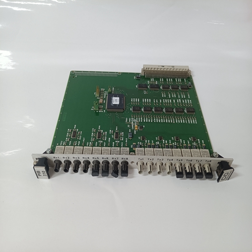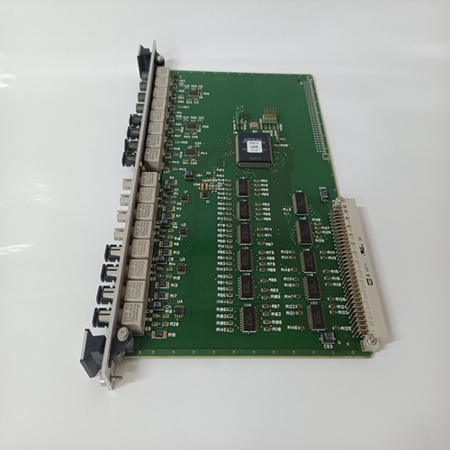
ALSTOM PIB310脈沖輸入卡件
該板僅包含電阻器,以增加緩沖電路的電源,其連接方式為:金屬對(duì)峙。
SDCS-PIR-21板用于以下設(shè)備:
電源接口板:
-500 V時(shí)的SDCS-PIN-22 450 A/520 A
-SDCS-PIN-24 450 A 600 V電源接口板用于C1和C2型DCS轉(zhuǎn)換器模塊結(jié)構(gòu)
正在使用不同的版本。使用的類型有:
500 V時(shí)100 A…700 A轉(zhuǎn)換的SDCS-PIN-205
-600 V時(shí)110 A…450 A轉(zhuǎn)換的SDCS-PIN-206
-500 V時(shí)100 A…1000 A轉(zhuǎn)換的SDCS-PIN-205B
-SDCS-PIN-206B,適用于600 V時(shí)110 A…450 A轉(zhuǎn)換
電路板從SDCS-PIN-20x循環(huán)更新
? 引腳20xA? PIN-20xB根據(jù)技術(shù)
要求和新的C2轉(zhuǎn)換器類型。這個(gè)SDCS-PIN20xB可替代SDCS-PIN-20x以及引腳20xA。
SDCS-PIN-20x板包括:
-帶脈沖變壓器的點(diǎn)火脈沖電路
-電樞電流的測(cè)量
-晶閘管保護(hù)用緩沖電路
(由晶閘管并聯(lián)的RC電路組成和剛果民盟網(wǎng)絡(luò))
-交流和直流高歐姆電壓測(cè)量
-負(fù)載電阻的額定電流標(biāo)度,零電流檢測(cè)和HW電壓類型編碼
-散熱器溫度測(cè)量接口帶PTC傳感器
-過電壓保護(hù)和電壓保險(xiǎn)絲
測(cè)量圖5.2/4 SDCS-PIN-20x、20xA、20xB板的布局。
-相同的電路板將用于三相磁場(chǎng)轉(zhuǎn)換器,無(wú)需任何修改
供給備件
電源部分的保護(hù)通過以下方式完成:RC電路。緩沖電路與每個(gè)晶閘管并聯(lián)連接,其間帶有保險(xiǎn)絲。RCD元件由保險(xiǎn)絲F 101至F 103保護(hù)。交流電壓測(cè)量從后面進(jìn)行保險(xiǎn)絲。
保險(xiǎn)絲數(shù)據(jù):巴斯曼KTK-R-6A(600V)
電源接口板SDCS-PIN205可以:用作SDCS-PIN-21、22和25.板SDCS-PIN-206可用作SDCS-PIN-23和24的替代品,但不能用作替代品!如果轉(zhuǎn)換器為450 a/520 a/
500 V時(shí)為700 A或600 V時(shí)為450 A的轉(zhuǎn)換器,必須考慮額外的動(dòng)作(SDCS-PIN-2x和引腳20x由圖5.2/3中編號(hào)為1、2和3的灰色陰影區(qū)域標(biāo)記)。
This board contains only resistors to increase the
power of the snubber circuit and it is connected by
metal standoffs.
The SDCS-PIR-21 board is used with the following
power interface boards:
- SDCS-PIN-22 450 A/520 A at 500 V
- SDCS-PIN-24 450 A at 600 V The power interface board is used for DCS converter modules construction type C1 and C2. There
are different versions in use. The used types are:
- SDCS-PIN-205 for 100 A...700 A Conv. at 500 V
- SDCS-PIN-206 for 110 A...450 A Conv. at 600 V
- SDCS-PIN-205B for 100 A...1000 A Conv. at 500 V
- SDCS-PIN-206B for 110 A...450 A Conv. at 600 V
The boards are cyclic updated from SDCS-PIN-20x
? PIN-20xA ? PIN-20xB according to the technical
requirements and the new C2 converter types. The
SDCS-PIN20xB can replace the SDCS-PIN-20x
and PIN-20xA.
The SDCS-PIN-20x board consists of:
- firing pulse circuits with pulse transformers
- measurement of the armature current
- snubber circuit for thyristor protection
(consists of RC circuits in parallel of the thyristors
and RCD network)
- AC and DC high ohmic voltage measurement
- rated current scaling with burden resistors, zero
current detection and HW voltage type coding
- interface for heat sink temperature measurement
with a PTC sensor
- fuses for overvoltage protection and voltage
measuring
Fig. 5.2/4 Layout of the SDCS-PIN-20x, 20xA, 20xB board.
- the same board will be used without any modification at a converter used for three-phase field
supply
Spare part
The protection of the power part is done by using
RC circuits. Snubber circuits are wired up in parallel to each thyristor with fuses in between. RCD elements are protected by the fuses F 101 to F 103.
The AC voltage measurement is taken from behind
the fuse.
Fuse data: Bussmann KTK-R-6A (600V)
The power interface board SDCS-PIN205 can be
used as a replacement of SDCS-PIN-21, 22 and
25. The board SDCS-PIN-206 can be used as a replacement of SDCS-PIN-23 and 24, but not viceversa! In case of a converter with 450 A / 520 A /
700 A at 500 V or a converter of 450 A at 600 V additional actions have to be taken into account (the
basic difference between the SDCS-PIN-2x and
PIN-20x is marked by the grey-shaded areas numbered 1,2 and 3 in fig. 5.2/3).


