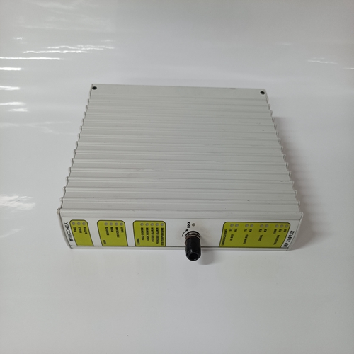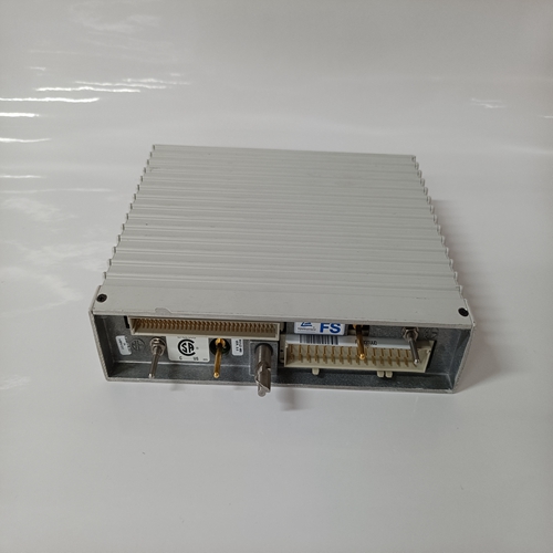
TRICONEX MP3101S2可編程控制模塊
穩定性控制:穩定電路是一個速率反饋RC網絡。
它包括電容器C4和C5、電阻器R7、R19和R20,以及穩定調整電位計R6。該RC網絡注入穩定
來自調節器輸出的信號,有助于防止發電機電壓振蕩。
低頻限值(UFL):UFL提供參考電壓
所述誤差檢測器在所述發電機輸出頻率高于預定極限頻率時是恒定的。當發電機操作慢于預定UFL操作閾值,
UFL將為誤差檢測器提供參考電壓,即:比例更低。
UFL的參考電壓由齊納二極管Z1提供標準50Hz、60Hz和400Hz KCR的UFL運行閾值
上面給出了760個調節器。各種組件的操作包括UFL組件的系統在以下段落中描述。
感測變壓器的電壓為直流? 由二極管D19和D21和直腸? ed信號應用于施密特觸發器,包括:運算放大器? er IC2A、電阻器R47至R51和電容器C29.在輸出端產生24 Vdc峰間方波IC2A,其頻率為感測電壓的兩倍。
來自施密特觸發器的24 Vdc方波被饋送至? rst兩級單穩態多諧振蕩器IC1的級及其相關
部分,其中在使感測電壓的頻率加倍。
5伏直流方波應用于單穩態多諧振蕩器的第二級
這個單穩態多諧振蕩器輸出脈沖振幅均勻每個輸入脈沖的持續時間。因此單穩態多諧振蕩器輸出端的集體脈沖為:與脈沖頻率成正比。單穩態
多諧振蕩器輸出饋入四極巴特沃斯低通? 過濾器由運算放大器組成? er IC2B和IC2C,電阻R60以及電容器C13至C18? 濾波電路來自單穩態的集體脈沖的實際平均值多諧振蕩器。放大? er增益設置在其輸出等于在額定60Hz或400Hz工作時,由電阻器R65,當在50Hz的額定頻率下操作時,通過拆下跨接線J1,將電路設置為50 Hz工作動作將R57添加到電路中。二極管D12和集成電路IC2D形成電壓箝位電路。如果來自巴特沃斯的電壓? lter等于齊納參考,錯誤檢測器的UFL輸出將與齊納參考和UFL對調節器操作沒有影響。
然而,當來自? lter在以下過程中降低:發電機的低速運行,施加的參考電壓到誤差檢測器的誤差小于齊納參考。這一行動將:使誤差檢測器差分信號按比例增加以一種方式,該方式將產生一個成比例的稍后接通信號調節器輸出SCR。然后,調節器降低勵磁和發電機輸出電壓降低。
The reference voltage to the UFL is supplied by Zener diode Z1. The UFL operational threshold for standard 50 Hz, 60 Hz, and 400 Hz KCR 760 regulators are given above. The operation of the various components comprising the UFL assembly is described in the paragraphs that follow. The voltage from the sensing transformer is recti? ed by diodes D19 and D21, and the recti? ed signal is applied to a Schmidt trigger consisting of operational ampli? er IC2A, resistors R47 through R51, and capacitor C29. A 24 Vdc peak-to-peak square wave is generated at the output of IC2A at double the frequency of the sensing voltage. The 24 Vdc square wave from the Schmidt trigger is fed to the ? rst stage of a two-stage monostable multivibrator IC1 and associated parts, where it is decreased to a 5 Vdc peak-to-peak square wave at double the frequency of the sensing voltage. The 5 Vdc square wave is applied to the second stage of the monostable multivibrator. The monostable multivibrator output pulse is uniform in amplitude and duration for each input pulse. Thus, the average voltage level of the collective pulses at the output of the monostable multivibrator is directly proportional to the frequency of the pulses. The monostable multivibrator output is fed into a four-pole Butterworth low pass ? lter comprised of operational ampli? er IC2B and IC2C, resistors R60 through R66, and capacitors C13 through C18. This ? ltering circuit does the actual averaging of the collective pulses from the monostable multivibrator. Ampli? er gain is set at level where its output equals the Zener reference at rated 60 Hz or 400 Hz operation by resistors R65, R66, and capacitor C16. When operated at rated frequency of 50 Hz, the circuit is set for 50 Hz operation by removing jumper J1. This action adds R57 to the circuit. Diode D12 and integrated circuit IC2D form a voltage clamping circuit. If the voltage from the Butterworth ? lter is equal to that of the Zener reference, the UFL output to the error detector will be the same as the Zener reference and the UFL will have no effect on regulator operation. However, when the voltage from the ? lter decreases as occurs during underspeed operation of the generator, the reference voltage applied to the error detector is less than the Zener reference. This action will cause the error detector differential signal to proportionally increase in a manner that results in a proportionally later turn-on signal to the regulator output SCRs. The regulator then decreases excitation and a lowering of generator output voltage occurs.


