


")
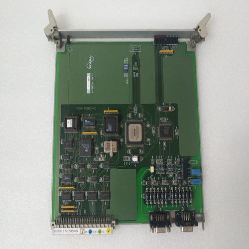
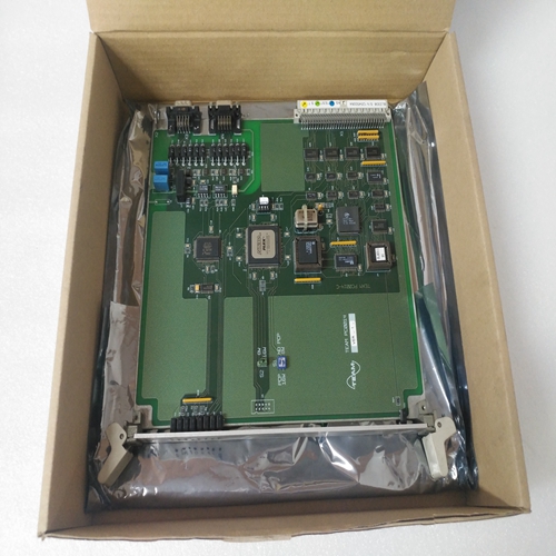
TEAM BL0308卡件
伺服驅(qū)動器也可以作為轉(zhuǎn)矩控制驅(qū)動器操作。
在主-從驅(qū)動或串聯(lián)驅(qū)動中主驅(qū)動器決定從驅(qū)動器的速度。這樣操作模式:扭矩設(shè)定點被轉(zhuǎn)移到設(shè)定點輸入
從速度控制的主驅(qū)動器到從驅(qū)動器。
應(yīng)注意,主驅(qū)動和從驅(qū)動的電機軸必須機械連接在一起,無間隙,以防止施加扭矩時,從動裝置在無負(fù)載扭矩的情況下加速。這聯(lián)軸器必須盡可能剛性和抗扭剛度,以防止:機械系統(tǒng)中的振動。
主驅(qū)動器和從驅(qū)動器之間的連接如所示圖。12至16.MOD編程模塊應(yīng)特別配置用于從驅(qū)動器。
系統(tǒng)或伺服驅(qū)動器中的故障無法在緊急停止情況。因此,在這種情況下,有必要隔離
通過主電源從主電源供電的驅(qū)動器電源部分接觸器,以便安全停止伺服驅(qū)動(通過打開緊急停止電路)。
在伺服驅(qū)動停止之前,必須始終假設(shè)存在故障,并且可能發(fā)生危險的駕駛移動,其程度取決于故障類型和發(fā)生時驅(qū)動器的運行狀態(tài)。
必須提供更高級別的安全措施,以確保驅(qū)動器:一般情況下,通過緊急停止電路斷開
故障如果單獨操作時必須降低驅(qū)動器的峰值扭矩
機器條件下,最大扭矩可從外部限制
由用戶通過Ired模擬輸入。在這種情況下,模擬電壓
應(yīng)用于Ired輸入。電壓URE的值取決于期望減小系數(shù)k=最大扭矩的減小扭矩:
URE=10伏?(1-k)減少的電機電流Ired的值可從圖。9和10.扭矩可根據(jù)電流計算
使用中電機的扭矩常數(shù)km,可從第10.1節(jié)中的表格:M=km?Ired
最小可調(diào)節(jié)扭矩被限制為最小值。這個相關(guān)的最小可調(diào)電機電流可從第10.2節(jié)中的表格。
如果Ired輸入沒有可用的模擬電壓,則扭矩減小值:電阻R(ex)可連接在Ired端子和通過繼電器觸點連接+15 VM端子。
The servo drive can also be operated as a torque-controlled drive.
In the master-slave drive or tandem drive the speed controller of the
master drive determines the speed of the slave drive. In such an
operating mode the torque set-point is transferred to the set-point input
of the slave drive from the speed-controlled master drive.
It should be noted that the motor shafts of the master and slave drives
must be mechanically coupled together without backlash to prevent the
slave drive accelerating without load torque when torque is applied. This
coupling must be as rigid and as torsionally stiff as possible to prevent
oscillations in the mechanical system.
Connections between the master drive and the slave drive are shown in
Figs. 12 to 16. The MOD programming module should be specially
configured for the slave drive.
A malfunction in the system or servo drive cannot be eliminated in an
emergency-stop situation. It is therefore necessary in this case to isolate
the power section of the drive from the mains supply via the mains
contactor in order to stop the servo drive safely (by opening the
emergency-stop circuit).
Until the servo drive is stopped it must always be assumed that faulty and
dangerous drive movement can occur, the extent of which depends on
the type of fault and the operating state of the drive at the time it occurs.
A higher-level safety measure must be provided to ensure that the drive
disconnected via the emergency-stop circuit in the event of a general
malfunction. If the peak torque of the drive has to be reduced for individual operating
conditions on the machine, the maximum torque can be limited externally
by the user via the Ired analogue input. In this case an analogue voltage
is applied to the Ired input. The value of the voltage Ured depends on the
desired reduction factor k = reduced torque to maximum torque:
Ured = 10 volts ? (1 - k)
The value of the reduced motor current Ired can be obtained from the
graphs in Figs. 9 and 10. The torque can be calculated from the current
torque constant km of the motor in use, which can be obtained from the
table in Section 10.1:
M = km ? Ired
The smallest adjustable torque is limited to a minimum value. The
associated minimum adjustable motor current can be obtained from the
table in Section 10.2.
If no analogue voltage is available for the Ired input, for a reduced torque
value a resistor R(ex) can be connected between the Ired terminal and
the +15 VM terminal via a relay contact.