


")
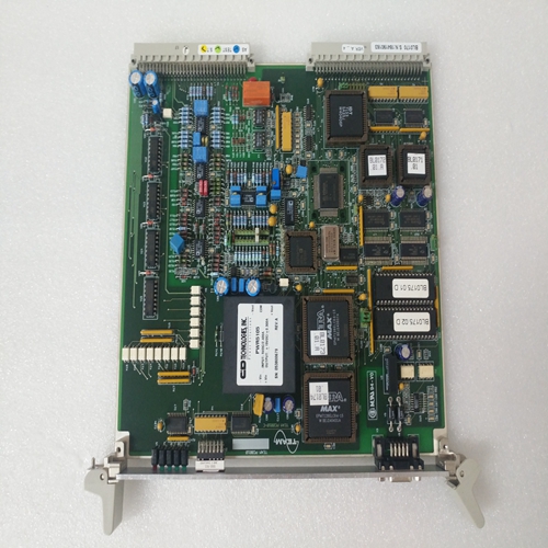
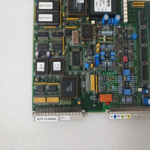
TEAM BL0170模塊
電源電壓施加后,驅動放大器發出信號
當它們“準備就緒”時,伺服驅動器可以通過以下方式以受控速度運行:–在射頻輸入端注入控制器啟用信號,以及–施加與電機成比例的模擬設定點電壓速度,跨輸入
?E1和E2或?E3和0虛擬機或?E4和0虛擬機。
可以進行以下設置:(參見圖8中的伺服驅動模塊)。
輸入E1-E2是差分輸入,輸入E3和E4是求和輸入它們被稱為0 VM。
速度加權(輸入靈敏度)已在中設置MOD編程模塊上的工廠。提供了兩種設施:電阻器和電位計值并入MOD根據所需的輸入權重對模塊進行編程使用者
編程模塊類型名稱的最后三位數字指定:輸入加權(見第3.2節)。
如果沒有可用的用戶數據,則MOD編程模塊將給出
每最大速度值10伏的輸入加權(無調整電位計)。
NC輸出的速度設定點可以平滑,如果樓梯功能明顯受到干擾。應該注意的是,過度平滑可以降低位置控制的動態響應,并且從而減慢反應時間。
設定點平滑只能通過使用微分來實現輸入E1-E2。通過將電容器C5焊接到
MOD編程模塊(最大可達3uF,對應于大約5至7ms的平滑時間常數)。
當電機順時針旋轉時,從輸出軸看旋轉方向如下:差分輸入E1-E2:E1處的電壓為正關于E2
對輸入E3、E4求和:E3或E4處的電壓為負關于0VM
T處的轉速計測量信號(感測):電壓相對于對于0VM,如果另一個旋轉方向是:
渴望的:–在差分輸入E1-E2處交換連接,如果使用,–通過連接端子X6/9和X6/10,反轉所有輸入的方向在控制放大器處。通過互換電機連接來反轉旋轉方向
這是不可能的,并導致驅動器故障。速度控制器具有極低的溫度漂移。零可以在底部的“調零”電位計上校正漂移前面板右側(第5.2.2節圖35至40中的前視圖)。應始終在初始操作和更換后檢查漂移
伺服驅動模塊:如果軸以零速度設定點移動,則軸的旋轉運動應通過上的“調零”電位計設置為零控制柜達到最終溫度時的前面板。
After the mains voltage has been applied and the drive amplifiers signal
that they are ?ready“, the servo drive can be run at controlled speed by
– injecting the controller enabling signal at the RF input and
– applying an analogue set-point voltage, that is proportional to the motor
speed, across the inputs
? E1 and E2 or
? E3 and 0 VM or
? E4 and 0 VM.
The following settings are possible: (see basic circuit diagram of the
servo drive module in Fig. 8).
Input E1-E2 is a differential input, inputs E3 and E4 are summing inputs
that are referred to 0 VM.
The speed weighting (input sensitivity) has already been set in the
factory on the MOD programming module. Two facilities are provided The resistor and potentiometer values are incorporated into the MOD
programming module according to the input weighting required by the
user.
The last three digits of the programming module type designation specify
the input weighting (see Section 3.2).
If no user data are available, the MOD programming module is given the
input weighting of 10 volts per max. speed value (no adjustment
potentiometer).The speed set-point output by the NC can be smoothed if the staircase
function becomes noticeably disturbed. It should be noted that excessive
smoothing can reduce the dynamic response of the position control and
thus slow the reaction time.
Set-point smoothing can be implemented only by using the differential
input E1-E2. Smoothing is provided by soldering a capacitor C5 onto the
MOD programming module (up to a maximum of 3uF is possible,
corresponding to a smoothing time-constant of approximately 5 to 7 ms).
With the motor rotating clockwise, as viewed from the output shaft, the
direction of rotation is as follows:
Differential input E1-E2: voltage at E1 is positive
with respect to E2
Summing inputs E3, E4: voltage at E3 or E4 is negative
with respect to 0VM
Tacho measuring signal at T(sense): voltage is positive with respect
to 0VM The following facilities are provided if another direction of rotation is
desired:
– Interchange the connections at differential input E1-E2, if this is used,
– Reverse the direction of all inputs by linking terminals X6/9 and X6/10
at the control amplifier.
Reversing the direction of rotation by interchanging motor connections
is not possible and causes the drive to malfunction.
The speed controller has an extremely low temperature drift. The zero
drift can be corrected on the ?ZERO ADJ“ potentiometer at the bottom
right of the front panel (front view in Figs. 35 to 40 in Section 5.2.2).
The drift should always be checked at initial operation and after replacing
the servo drive module:
If the axis moves with a zero speed set-point, the rotary motion of the axis
should be set to zero by means of the ?ZERO ADJ“ potentiometer on the
front panel when the control cabinet has reached its final temperature.