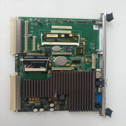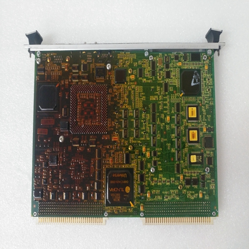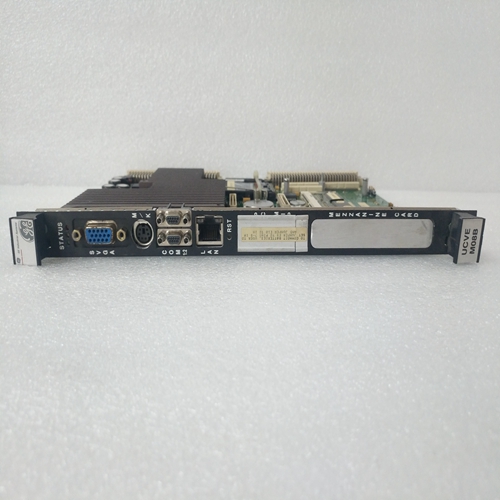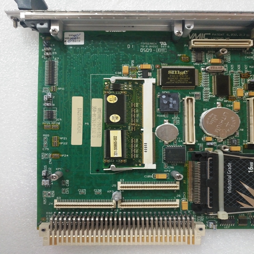
IS215UCVEM08B燃機模塊
模擬輸入模塊提供多達32個低電壓或電流模擬輸入信號。全部的模塊的通道輸入彼此電阻隔離,并電流隔離來自系統環境。基本模塊可以配置為滿足一系列輸入規格,不同的配置可從模塊類型編號中識別(見第1.3節,規范)。電路三重化和表決程序使模塊具有單容錯性。前面板信道選擇器和測試點可對任何信道進行計量,指示器顯示電路在線狀態和模塊的健康狀況。
與“熱修復”兼容的模塊可安裝在SC300E機箱通過物理編碼防止“錯誤開槽”。SC300E系統軟件通過內置硬件標識符識別模塊。通道輸入通過機箱上的DIN 41612“后插拔”系統連接至模塊背板。本文件旨在提供對模擬輸入模塊,足以使基本維護操作在場物理模擬輸入模塊是一個9U高PCB,帶有集成前面板和后連接器;
一插件子板承載公共接口電路。
總平面圖、位置連接器、前面板組件和321/320配置鏈路如圖1-1所示。機械編碼塊所有輸入/輸出模塊都帶有兩個機械編碼塊,配備有匹配的引腳機箱中的相應塊中有孔,防止模塊插入錯誤的插槽。模塊塊中的引腳在工廠按照以下方式安裝:將模塊和相應的固定螺釘從機箱編碼塊上拆下,以便:啟用安裝。未使用的孔用固定螺釘堵塞。底盤機械編碼該模塊的模塊配置如圖2-1所示。現場電路圖2-2所示的現場輸入回路是安全所需的絕對最小值模擬輸入的連接。但是,我們建議使用他們的16信道模擬輸入終端卡TAI16***,可提供現場電源、遠程和本地報警指示、瞬態抑制、信號和保護接地設施。
圖2-3顯示了電流輸入模塊的終端卡。操作模式321或320模式設置了閾值,該閾值決定了電路的容量
降級,同時仍保持整體操作。設置320模式意味著系統
將在三個可維修電路中的兩個電路上繼續工作;如果這個數字下降到1:1在三個數據中,最后讀取的數據被保持。在321模式下,系統將繼續運行:三分之一的可維修電路;如果失敗,則保持最后讀取的數據,并且模塊離線。
PURPOSE
The Analogue Input Module provides up to 32, low voltage or current analogue input signals. All
channel inputs into the module are resistively isolated from each other and galvanically isolated
from the system environment.
The basic module can be configured to meet a range of input specifications, the different
configurations can be identified from the module type number (see Section 1.3, Specification).
Circuit triplication and voting procedures make the module single-fault tolerant. A front panel
Channel selector and test points enable the metering of any channel, and indicators show the
circuit on-line status and the health of the module.
The module, which is compatible with ‘hot repair’, can be fitted in any of the ten I/O slots in the
SC300E Chassis, ‘wrong slotting’ is prevented by physical coding. The SC300E system
software identifies the module via a built-in hardware identifier.
Channel inputs are wired to the module via the DIN 41612 ‘rear plug-up’ system on the chassis
backplane. This document is intended to provide a general understanding of the function of the
Analogue Input Module, sufficient to enable basic maintenance operations to be effected in the
field.PHYSICAL
The Analogue Input Module is a 9U high PCB with integral front panel and rear connectors; a
plug-in daughter board carries the Common Interface circuits.The general layout, location of the
connectors, front panel components and the 321/320 configuration link is shown in Figure 1-1.
Mechanical coding blocks
All Input/Output modules carry two mechanical coding blocks equipped with pins which mate
with holes in corresponding blocks in the chassis and prevent the module being inserted into
the wrong slot. The pins in the module blocks are factory installed in a pattern determined by
the module and corresponding set screws are removed from the chassis coding blocks to
enable fitting. Unused holes are plugged with set screws. The chassis mechanical coding
block configuration for this module is shown in Figure 2-1.Field circuits
The field input loop shown in Figure 2-2 is the absolute minimum required for the safe
connection of analogue inputs. We however, recommend the use of their 16 Channel
Analogue Input termination cards TAI16*** which can offer field power supplies, remote and
local alarm indication, transient suppression and signal and protective ground facilities.
Figure 2-3 shows a termination card for a current input module.Modes of operation
The 321 or 320 mode sets the threshold that determines how much of the circuit can be
degraded while still preserving overall operation. Setting the 320 mode means that the system
will continue to function with two out of three serviceable circuits; if the number falls to one out
of three the last read data is maintained. In 321 mode the system will continue to function with
one out of three serviceable circuits; if that fails the last read data is maintained and the
module is taken off-line.


