


主營產(chǎn)品
PLC可編程控制器模塊,DCS卡件,ESD系統(tǒng)卡件,振動監(jiān)測系統(tǒng)卡件,汽輪機控制系統(tǒng)模塊,燃氣發(fā)電機備件等,優(yōu)勢品牌:Allen Bradley、BentlyNevada、ABB、Emerson Ovation、Honeywell DCS、Rockwell ICS Triplex、FOXBORO、Schneider PLC、GE Fanuc、Motorola、HIMA、TRICONEX、Prosoft等各種進口工業(yè)零部件
產(chǎn)品廣泛應用于冶金、石油天然氣、玻璃制造業(yè)、鋁業(yè)、石油化工、煤礦、造紙印刷、紡織印染、機械、電子制造、汽車制造、塑膠機械、電力、水利、水處理/環(huán)保、鍋爐供暖、能源、輸配電等等
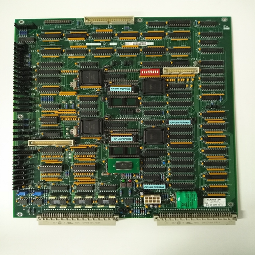
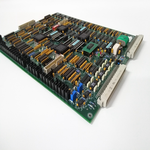
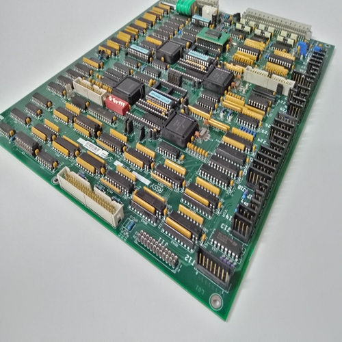
ELEMASTER IB3110551工控模塊
所有軟件配置,即保護功能的選擇和設置以及輸入和通過RS-423串行接口在216VC62a處理單元。相應的連接器是裝置前部的25針插座X2,個人計算機已連接。
2.2.2.216MB66型設備機架布局圖2.2顯示了電子設備的布置示例設備機架中的單元。設備機架被細分
分成21個分部(T)。第1-3部分和第19-21部分始終用于:輔助直流電源裝置216NG61、216NG62或216NG63原則上,如果系統(tǒng)電纜連接已相應安裝,則電子單元可位于剩余的分區(qū)4-18中的任何分區(qū)中。然而,出于標準化的原因,各種類型的裝置始終位于設備機架中的同一位置。有關特定工廠216MB66設備機架中電子單元的布局,請參閱特定的一組圖表。
表2.1給出了各種裝置的標準槽參考。
例如,最多兩個216VC62a處理單元可以安裝在設備機架中,并始終位于插槽中4和6。
I/P的I/O信號的名稱和編號
保護系統(tǒng)的O/P單元在“I/O”列中給出通道定義”。請注意,給定的I/O通道數(shù)量
對于每組相同類型的裝置,指的是設備機架,而不是整個系統(tǒng)。總數(shù)量
整個系統(tǒng)的I/O通道由I/O數(shù)量給出已安裝的機組(另見第2.2.3節(jié)和一組特定設備圖)替代系統(tǒng)版本
保護中使用的電子單元和I/O單元的數(shù)量系統(tǒng)根據(jù)工廠要求而變化。最大值
一個系統(tǒng)中的電子單元數(shù)量(單個216MB66設備機架)如表2.1所示。
表中列出的版本的I/O信號數(shù)量
2.2至表2.4,指完整系統(tǒng)(單個系統(tǒng)一個216MB66設備機架)。設備機架可容納一個或兩個216VC62a處理單元,因此表2.2至表2.4中給出的版本總計計算能力為425%或850%。
All software configuration, i.e. selection and setting of the protection functions and the assignment of signals to the inputs and
outputs, is performed via the RS-423 serial interface on the
216VC62a processing unit. The corresponding connector is the
25 pin socket X2 on the front of the unit, to which a personal
computer is connected.
2.2.2. Layout of equipment rack Type 216MB66
Fig. 2.2 shows an example of the arrangement of the electronic
units in the equipment rack. The equipment rack is sub-divided
into 21 divisions (T). Divisions 1-3 and 19-21 are always used for
auxiliary d.c. supply units 216NG61, 216NG62 or 216NG63. In
principle, the electronic units may be located in any of the remaining divisions 4-18, providing that the system cable connections were correspondingly installed. For reasons of standardisation, however, the various types of units are always located at the same position in the equipment rack.Consult the specific set of diagrams for the layout of the electronic units in the 216MB66 equipment rack of a particular plant.
Table 2.1 gives the standard slot references for the various units.
For example, a maximum of two 216VC62a processing units can
be installed in an equipment rack and are always located in slot
4 and 6.
The designations and numbering of the I/O signals for the I/P
and O/P units of a protection system are given in the column "I/O
channel definition". Note that the quantity of I/O channels given
for each group of the same type of units refers to the particular
equipment rack and not the entire system. The total quantity of
I/O channels for the entire system is given by the number of I/O
units installed (see also Section 2.2.3. and the set of specific
plant diagrams)Alternative system versions
The number of electronic units and I/O units used in a protection
system varies according to plant requirements. The maximum
quantities of electronic units in one system (a single 216MB66
equipment rack) are given in Table 2.1.
The numbers of I/O signals given for the versions listed in Table
2.2 to Table 2.4 refer to a complete system (single system with
one 216MB66 equipment rack). An equipment rack can accommodate one or two 216VC62a processing units and therefore the
versions given in Table 2.2 to Table 2.4 can have a total
computing capacity of 425% or 850%.