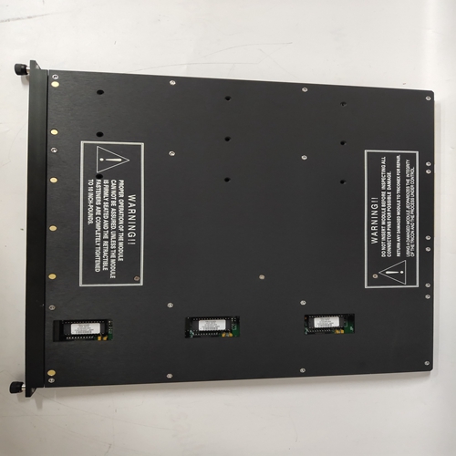
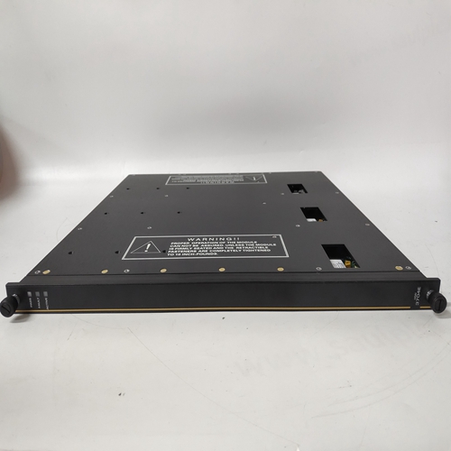
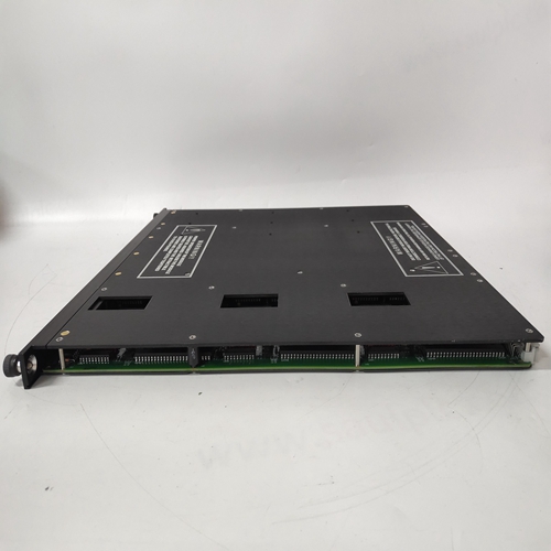
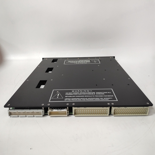
TRICONEX 3704E工控接口模塊
10.1.4自動/手動
在FCO101中,A/M模塊配置為將閥門控制從自動PID控制器切換到脈沖發生器手動旋鈕。按下A/M按鈕,在(Loop01.S)設定點參數和(Loop01.V)閥門參數。在手動顯示閥門參數的同時轉動脈沖發生器旋鈕,以改變數值顯示器和水平條形圖上的值;旋轉脈沖發生器旋鈕,同時顯示設定點參數以更改數值和垂直S條形圖。10.1.5修改FCO除了FCO101單回路控制外,還有幾個其他出廠配置選項可用,例如比率設定控制(FCO105)和級聯控制(FCO 121)。要下載另一個FCO,請執行中的步驟第2.7節。可以通過添加和刪除功能塊或更改默認值來更改FCO參數值。配置路線圖如第2節所示。請注意,X表示按下步驟向下或向上按鈕,a<>表示轉動脈沖發生器旋鈕。例如,要添加功能塊,您可以
將執行以下步驟:
1.按ENTER/EXIT CONF。
2.按下“向下”鍵,直到顯示視圖。
3.轉動脈沖發生器旋鈕,直到顯示ADD FB。
4.按下“功能塊”菜單的“下一步”。
5.轉動脈沖發生器旋鈕,滾動瀏覽可用功能塊,然后按存儲添加功能塊配置。6.要更改功能塊參數,請將脈沖發生器旋鈕轉到編輯FB。7.按下“功能塊”菜單的“下一步”。
8.將脈沖發生器旋鈕轉到所需功能塊,然后按下“步進”。
9.將顯示第一個功能塊參數。例如,A/M傳輸塊的RG PTR或模擬輸入塊的最小刻度。按“向下”鍵顯示當前參數值,或使用脈沖發生器旋鈕,用于選擇不同的參數。按存儲保存所有更改。
10.按退出按鈕返回正常操作模式。
請注意,FCO101中的SETPT、報警、PID和ODC功能塊都將AIN1稱為RG PTR(范圍指針)以確定功能塊的操作范圍。請注意,對配置可能需要更改引用的RG PTR。例如,在FCO105(比率設定控制)中控制器輸出范圍由AIN2的范圍確定。嘗試使用配置路徑將模擬輸入#1(AIN1)的默認0-100%范圍更改為100.0-500.0°F
第2節中的映射或以下步驟:
1.按ENTER/EXIT CONF以顯示循環。
2.按兩次“向下”以顯示視圖。
3.轉動脈沖發生器旋鈕或使用箭頭按鈕顯示編輯FB。
4.按下“下一步”以顯示功能塊菜單。
5.轉動脈沖發生器旋鈕或使用右箭頭按鈕顯示AIN1。
6.按“向下”鍵顯示最小刻度。
7.按下“逐步下降”以顯示當前0%的范圍。
8.轉動脈沖發生器旋鈕,在最后一位顯示1。顯示應為“0.00001”。
9.現在按下左箭頭(標記)按鈕。請注意,每次
按鈕被按下。按下箭頭按鈕,直到顯示屏顯示“100.000”,然后按下存儲按鈕。
10.1.4 Auto/Manual
In FCO101, the A/M block is configured to switch Valve control from the PID controller in AUTO, to the Pulser
Knob in Manual. Press the A/M button to toggle the display between the (Loop01.S) setpoint parameter and the
(Loop01.V) valve parameter. Turn the pulser knob while displaying the valve parameter in manual to change the
value on the numeric display as well as the horizontal bargraph; turn the pulser knob while displaying the setpoint
parameter in Auto to change the numeric value and the vertical S bargraph.
10.1.5 Modifying an FCO
In addition to FCO101, Single Loop Control, there are several other factory configured options available, such as
Ratio Set Control (FCO105) and Cascade Control (FCO121). To download another FCO follow the steps in
Section 2.7.
Changes to an FCO may be made either by adding and deleting function blocks or by changing the default
parameter values. A Configuration Road Map is shown in Section 2. Note that an X represents pressing the STEP
DOWN or STEP UP button and a <> represents turning the pulser knob. For example, to add a function block you
would do the following steps:
1. Press ENTER/EXIT CONF.
2. Press STEP DOWN until VIEW is displayed.
3. Turn the pulser knob until ADD FB is displayed.
4. Press STEP DOWN for the function block menu.
5. Turn the pulser knob to scroll through the available function blocks and press STORE to add the function block
to the configuration. 6. To make changes to a function block parameter turn the Pulser Knob to EDIT FB.
7. Press STEP DOWN for the function Block menu.
8. Turn the pulser knob to the desired Function Block and Press STEP DOWN.
9. The first function block parameter will be displayed. For example, RG PTR for the A/M Transfer Block or
MINSCALE for the Analog Input Block. Press STEP DOWN to display current parameter value or use the
pulser knob to select a different parameter. Press STORE to save any changes.
10. Press EXIT to return to normal operation mode.
Notice that the SETPT, ALARM, PID, and ODC function blocks in FCO101 all refer to AIN1 as the RG PTR
(range pointer) to determine the operating range of the function block. Be aware that making changes to a
configuration may require changing referenced RG PTRs. For example, in FCO105 (Ratio Set Control), the PID
controller output range is determined by the range of AIN2.
Try changing the default 0-100% range of analog input #1 (AIN1) to 100.0-500.0°F using the Configuration Road
Map in Section 2 or the following steps:
1. Press ENTER/EXIT CONF to display LOOP.
2. Press STEP DOWN twice to display VIEW.
3. Turn pulser knob or use arrow button to display EDIT FB.
4. Press STEP DOWN to display Function Block menu.
5. Turn the pulser knob or use right arrow button to display AIN1.
6. Press STEP DOWN to display MINSCALE.
7. Press STEP DOWN to display current 0% of range.
8. Turn the pulser knob to display 1 in the last digit. Display should read “0.00001”.
9. Now press the left arrow (TAG) button. Notice that the decimal place will move one place every time the
button is pressed. Press the arrow button until the display reads “100.000” and press the STORE button.


