


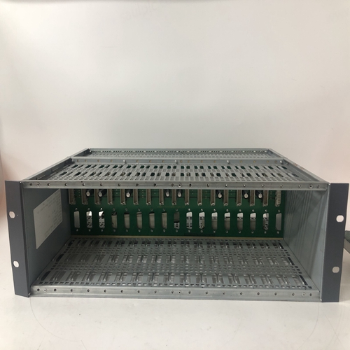
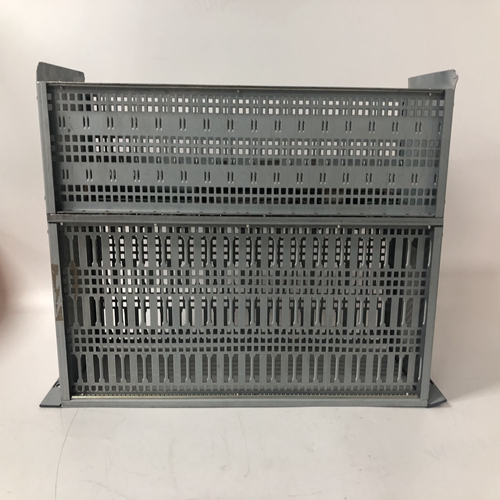
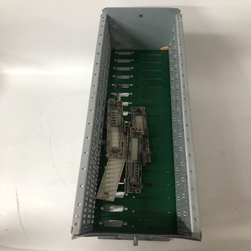
HONEYWELL 05701-A-0511邏輯框架
提供壓接連接器,用于將量程電阻器和信號輸入線插入
相同的連接器端子。當兩條不同規格的導線會出現以下情況時,也應使用連接器:否則可插入單個連接器端子中。對每個模擬輸入執行以下步驟。
1.選擇模擬輸入端子對,用于連接輸入信號布線。參考表8.1和如有必要,請參見下圖。
對于4-20 mA輸入,請轉至步驟2。對于1-5 Vdc或毫伏輸入,請轉到步驟4。僅4-20毫安輸入-選擇250? (對于AIN#)或3.75? (適用于阿伊努#)安裝套件中的電阻器,并用一塊將彎曲的電阻器引線絕緣指袖子。在引線端,約1/4英寸(6毫米)至5/16英寸(8毫米)裸露的電阻引線應露出。
如果要使用壓接接頭,則轉至步驟3。否則,轉至步驟4。3.壓接接頭-將電阻引線和任何信號線插入接頭,直到導線端在接頭的針腳端可見。使用標準電氣接頭壓接工具壓接連接。是確保所有電阻引線和信號輸入線都插入壓接前的連接器。
4.使用刀片寬度為1/8“(3 mm)的一字螺絲刀松開兩個端子螺釘。插入導線、電阻引線或接頭針腳上的壓接件插入接頭側面的兩個開口中選擇的終端號碼。
5.檢查所有相關部件和站接線是否完全插入,并小心地將螺釘擰緊至5在里面磅。不要過度擰緊。
6.對每個4-20 mA、1-5 Vdc和毫伏輸入重復步驟1-5。
7.小心地修整電阻器和接線,以便不會在部件、導線或連接上施加過大的應力。
8.4.3模擬輸出接線(4-20 mA,1-5 Vdc)
模擬輸出功能塊為AOUT1、AOUT2和AOUT3。圖8-12顯示了外部
接受4-20 mA的設備。對于需要1-5 Vdc的外部設備,請參見圖8-13。參考第8.4.2節接線指南。
8.4.4數字輸入和輸出接線
數字輸入和數字輸入通用功能塊的連接如圖8-14所示
顯示了內部和外部電源。半導體器件可以代替所示的機械開關。
布線指南見第8.4.2節。
數字輸入共用線,例如DIN1(-)與站公用線和外殼/安全接地隔離。
數字輸出接線如圖8-15所示。提供了三個電流和電壓輸出圖。
注意圖8-15C中瞬態抑制二極管的使用。始終安裝瞬態抑制部件
以保護摩爾353中的半導體器件。
數字輸出公共線DOUTC連接到站公共線。
Crimp-on connectors are provided for use when a range resistor and a signal input wire are to be inserted in the
same connector terminal. A connector should also be used when two wires of significantly different gauges would
otherwise be inserted in a single connector terminal.
Perform the following steps for each analog input.
1. Select an analog input terminal pair for connection of the input signal wiring. Refer to Table 8.1 and the
following illustrations as necessary.
For a 4-20 mA input, go to step 2. For a 1-5 Vdc or millivolt input, go to step 4. 4-20 mA Input Only - Select a 250? (for AIN#) or 3.75? (for AINU#)
resistor from the installation kit and insulate the bent resistor lead with a piece
of sleeving. At the lead end, approximately 1/4" (6 mm) to 5/16" (8 mm) of
bare resistor lead should be exposed.
If a crimp-on connector is to be used, go to step 3. Otherwise, go to step 4. 3. Crimp-On Connector - Insert the resistor lead and any signal wiring into the
connector until the wire ends are visible at the pin end of the connector.
Use a standard electrical connector crimp tool to crimp the connection. Be
certain that all resistor leads and signal input wires are inserted in the
connector before crimping.
4. Loosen the two terminal screws using a straight blade screwdriver with a 1/8" (3 mm) blade width. Insert
wires, resistor leads, or a crimp-on connector pin into the two openings in the side of the connector adjacent to
the selected terminal numbers.
5. Check that all involved components and station wiring are fully inserted and carefully tighten the screws to 5
in. lbs. Do not over tighten.
6. Repeat steps 1-5 for each 4-20 mA, 1-5 Vdc and millivolt input.
7. Carefully dress resistors and wiring so that excessive stress is not placed on a component, wire, or connection.
8.4.3 Analog Output Wiring (4-20 mA, 1-5 Vdc)
Analog output functions blocks are AOUT1, AOUT2, and AOUT3. Figure 8-12 shows connections for an external
device that accepts 4-20 mA. For an external device that needs 1-5 Vdc, see Figure 8-13. Refer to Section 8.4.2 for
wiring guidelines.
8.4.4 Digital Input and Output Wiring
Connections to Digital Input and Digital Input Universal function blocks are shown in Figure 8-14. Wiring for
internal and external power sources is shown. Semiconductor devices can replace the mechanical switches shown.
Wiring guidelines are found in Section 8.4.2.
Digital input commons, e.g. DIN1 (-), are isolated from station common and from case/safety ground.
Digital output wiring is shown in Figure 8-15. Three diagrams are provided showing current and voltage outputs.
Note the use of transient suppression diodes in Figure 8-15C. Always install a transient suppression component
across a reactive component, such as a relay coil, to protect the semiconductor devices in the Moore 353.
Digital output common, DOUTC, is connected to station common.