


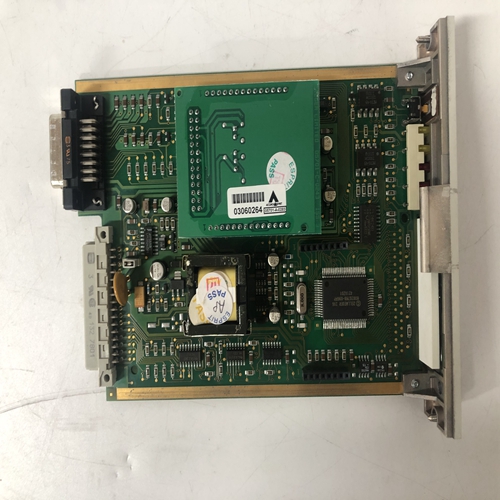
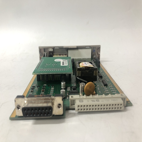
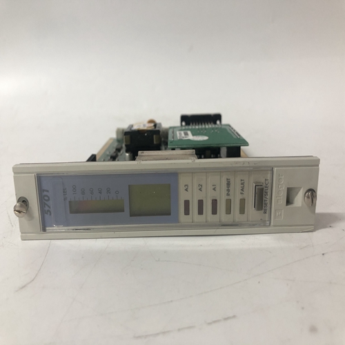
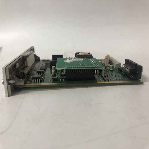
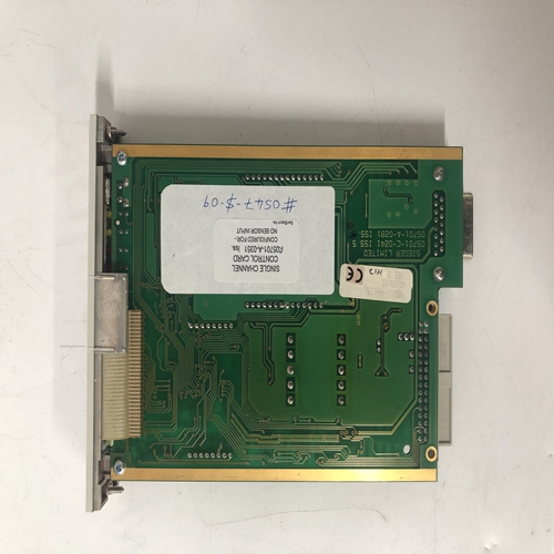
HONEYWELL 05701-A-0351輸出卡件
壓接(無焊接)連接器-當兩條或多條導線或導線和部件引線的組合應插入外殼后部的連接器端子中。電線
導線壓接在連接器中,連接器引腳插入選定的連接器端子。連接器可以提供更安全的涉及多條導線時的連接。其使用示例見正當各種Moore 353中提供了多個壓接連接器安裝套件,可從大多數電源獲得。
布線和導管-直流布線應與交流布線分開,并遠離交流供電按鈕、報警器、報警器、電機、螺線管和類似裝置。導管和電纜管道通常為:用于布線面板布線。未安裝在導管或電纜管道中的接線應夾緊或支撐
大約每12英寸(300毫米)。筆記:1.端子號顯示在每個連接器上。連接器的插入部分用外殼包裝。連接器是鍵控的。
2.外殼/安全接地-連接到后端子區域頂部中心的綠色螺釘。
3.NCA和NCB-連接LIL雙軸電纜或雙絞線。有關更多詳細信息,請參閱第8.4.9節。
4.IOA和IOB-LonWorks總線連接。雙絞線是典型的。
5.接地總線-外部用戶提供的接地總線可以簡化多個接地的連接,特別是在以下情況下
雙軸電纜屏蔽應接地。
1.端子字母和數字打印在各個連接器上。型號353_1_N…有2個連接器;模型
353_2_1…具有4個連接器和一個I/O擴展板。(下劃線是占位符/通配符;省略號指示后續字符不影響選擇。)
2.外殼/安全接地-連接至后端子區域頂部中心的綠色螺釘。
3.NCA和NCB-連接LIL雙軸電纜或雙絞線。有關更多信息,請參閱第8.5節信息
4.IOA和IOB-LonWorks總線連接。雙絞線是典型的。
5.接地總線-外部用戶提供的接地總線可以簡化多個接地的連接,特別是在以下情況下雙軸電纜屏蔽應接地。8.4.2模擬信號輸入接線(4-20 mA、1-5 Vdc和mV)
Moore 353模擬信號輸入端子連接到系統內的軟件功能塊AIN和AINU控制器。表8.1關聯了功能塊和輸入端子。這些終端將接受多個輸入具有適當布線和組件的信號類型。AIN或AINU功能塊的電流輸入信號必須通過量程電阻器轉換為1-5 Vdc。
輸入類型功能塊(1)范圍電阻器(2)圖
4-20 mA AIN1-4 250? 8-9和8-10AINU1和2 3.75? 8-11A
1-5 Vdc AIN1-4不需要8-9和8-10毫伏AINU1和2不需要8-11B
筆記:(1) 功能塊AIN4、AINU1和AINU2僅在I/O擴展器板為安裝。
(2) 所列量程電阻器在安裝套件中提供。對于其他當前值,請選擇一個范圍提供1-5 Vdc輸入的電阻器。例如,對于10-50 mA,安裝100? 范圍電阻。
Crimp-On (solderless) Connectors - A pin-style crimp-on connector can be used when two or more wires or a
combination of wires and component leads are to be inserted into a connector terminal at the rear of the case. Wires
and leads are crimped in the connector and the connector pin inserted in the
selected connector terminal. The connector can provide a more secure
connection when multiple leads are involved. An example of its use is shown at
right. Several crimp-on connectors are provided in various Moore 353
installation kits, and they are available from most electrical supply sources.
Wire Routing and Conduit - DC wiring should be separated from AC wiring and away from AC powered
pushbuttons, alarms, annunciators, motors, solenoids, and similar devices. Conduit and raceways are commonly
used for routing panel wiring. Wiring not installed in conduit or raceway should be clamped or supported
approximately every 12 inches (300 mm). Notes:
1. Terminal numbers are shown on each connector. The plug-in portions of the connectors are packed with a case.
The connectors are keyed.
2. Case/Safety Ground - Connect to green screw at top center of rear terminal area.
3. NCA and NCB - Connect LIL Twinaxial Cable or twisted pair wiring. Refer to Section 8.4.9 for additional details.
4. IOA and IOB - LonWorks bus connections. Twisted pair wiring is typical.
5. Ground Bus - An external, user-supplied ground bus can ease connection of multiple grounds, particularly when
twinaxial cable shields are to be grounded. 1. Terminal letters and numbers are printed on individual connectors. Model 353_1_N… has 2 connectors; Model
353_2_1… has 4 connectors and an I/O Expander board. (Underscore is a placeholder/wildcard; ellipsis
indicates that subsequent characters do not affect selection.)
2. Case/Safety Ground - Wire to green screw at top center of rear terminal area.
3. NCA and NCB - Connect LIL Twinaxial Cable or twisted pair wiring. Refer to Section 8.5 for additional
information.
4. IOA and IOB - LonWorks bus connections. Twisted pair wiring is typical.
5. Ground Bus - An external, user-supplied ground bus can ease connection of multiple grounds, particularly when
twinaxial cable shields are to be grounded.8.4.2 Analog Signal Input Wiring (4-20 mA, 1-5 Vdc, and mV)
Moore 353 analog signal input terminals are connected to software function blocks AIN and AINU within the
controller. Table 8.1 correlates function blocks and input terminals. These terminals will accept several input
signal types with the appropriate wiring and components. A current input signal to an AIN or AINU function block
must be converted to 1-5 Vdc by a range resistor.
INPUT TYPE FUNCTION BLOCKS(1) RANGE RESISTOR(2) FIGURE
4-20 mA AIN1-4 250? 8-9 and 8-10
AINU1 and 2 3.75? 8-11A
1-5 Vdc AIN1-4 Not Required 8-9 and 8-10
Millivolt AINU1 and 2 Not Required 8-11B
Notes:
(1) Function blocks AIN4, AINU1, and AINU2 are available only when an I/O Expander Board is
installed.
(2) Range resistors listed are supplied in Installation Kits. For other current values, select a range
resistor that will provide a 1-5 Vdc input. For example, for 10-50 mA, install a 100? range
resistor.