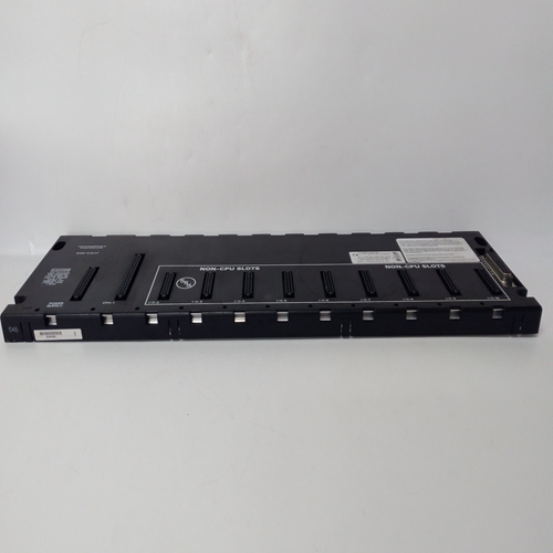
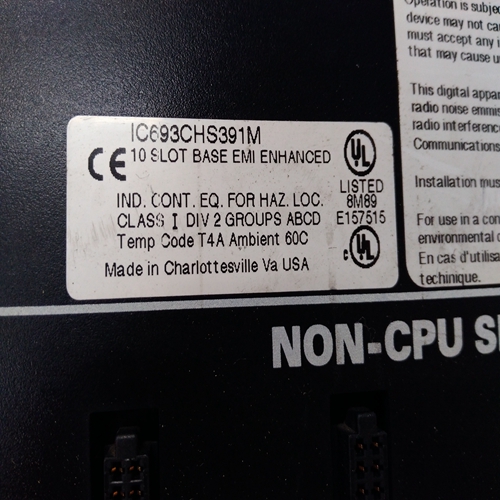
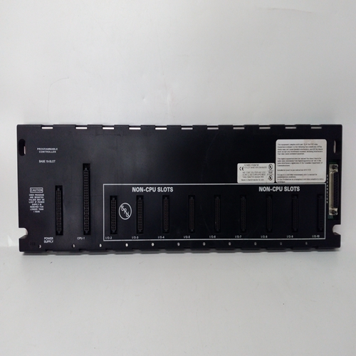
IC693CHS391庫(kù)存?zhèn)浼?/h1>
安裝本節(jié)描述了Moore 353過(guò)程自動(dòng)化控制器的安裝。主題包括:安裝
注意事項(xiàng)以及機(jī)械和電氣安裝。
重要的安裝必須符合國(guó)家電氣規(guī)范和所有其他要求適用的施工和電氣規(guī)范。
第1.4.4節(jié)列出了典型控制器裝運(yùn)中的項(xiàng)目清單。如果顯示器部件或電路板
必須安裝在外殼中,有關(guān)安裝信息,請(qǐng)參閱第11.5節(jié)“組件更換”,包括任何相關(guān)跳線的設(shè)置。
如有必要,請(qǐng)參閱第14.10節(jié)“機(jī)構(gòu)批準(zhǔn)”。CSA危險(xiǎn)場(chǎng)所預(yù)防措施和特殊安全使用條件包括在本節(jié)中。設(shè)備的使用方式未經(jīng)制造商可能會(huì)損害設(shè)備提供的保護(hù)。
8.1安裝注意事項(xiàng)
Moore 353用于室內(nèi)或室內(nèi)無(wú)振動(dòng)儀表板或機(jī)架中的嵌入式面板安裝一個(gè)隱蔽的地方。在單站面板切口中安裝單個(gè)控制器,或在中一行中安裝多個(gè)控制器多工位面板斷路器。對(duì)于水密面板,將每個(gè)控制器安裝在一個(gè)單站切口中。
控制器提供了“直接進(jìn)入連接器”或“側(cè)面進(jìn)入連接器”,第8.3節(jié)機(jī)械安裝中顯示了面板切口尺寸和控制器總體尺寸。控制器可以安裝在用戶提供的外殼中,位于室外或其位置:環(huán)境參數(shù)超過(guò)控制器操作規(guī)范。通常使用一條薄薄的硅密封膠在控制器的顯示器組件和安裝面板之間,以防止空氣或液體在該接頭處泄漏。
請(qǐng)勿將控制器安裝在陽(yáng)光直射可能撞擊面板或外殼的地方。陽(yáng)光直射可以使顯示器難以讀取,會(huì)干擾散熱。
水平或向后傾斜安裝控制器(即外殼前部高于后部)。如果控制器應(yīng)安裝一些電子記錄器或氣動(dòng)記錄器或工作站,后傾這些單元的限制可能會(huì)影響面板設(shè)計(jì)和布局。
通過(guò)清晰標(biāo)記的斷路器、保險(xiǎn)絲或開(kāi)關(guān)將電力輸送至控制器位于控制器附近,操作員可接近。斷路器或開(kāi)關(guān)應(yīng)位于非爆炸性環(huán)境中,除非適用于爆炸性環(huán)境。熱電偶輸入與I/O擴(kuò)展板和參考結(jié)溫度傳感器相適應(yīng)。在工廠,范圍電阻器和參考安裝套件中包括兩個(gè)參考接頭。第11.3節(jié)“故障排除”和第11.5節(jié)“組裝”討論了MPU控制器板上的跳線替換安裝或存儲(chǔ)控制器或MPU控制器板時(shí),請(qǐng)參閱本材料。
8.2環(huán)境考慮
在其環(huán)境規(guī)范范圍內(nèi)運(yùn)行控制器,以幫助確保可靠、無(wú)故障運(yùn)行
最小停機(jī)時(shí)間。參考第14.8節(jié)了解控制器工作溫度限制、工作濕度和最大含水量。
INSTALLATION This section describes installation of a Moore 353 Process Automation Controller. Topics include: installation considerations and mechanical and electrical installation. IMPORTANT The installation must conform to the National Electrical Code and all other applicable construction and electrical codes. Section 1.4.4 has a list of the items in a typical controller shipment. If the Display Assembly or a circuit board(s) must be installed in the case, go to Section 11.5 Assembly Replacement for installation information, including the setting of any involved jumpers. Refer to Section 14.10 Agency Approvals as necessary. CSA Hazardous Location Precautions and Special Conditions for Safe Use are included in this section. Use of the equipment in a manner not specified by the manufacturer may impair the protection provided by the equipment. 8.1 INSTALLATION CONSIDERATIONS A Moore 353 is intended for flush panel mounting in a vibration free instrument panel or rack in an indoor or sheltered location. Mount a single controller in a single-station panel cutout or mount several controllers in a row in a multiple-station panel cutout. For a watertight panel, mount each controller in a single-station cutout. Controllers have been supplied with either “direct entry connectors” or “side entry connectors.” Connector types, panel cutout dimensions, and overall controller dimensions are shown in Section 8.3 Mechanical Installation. The controller can be mounted in a user-supplied enclosure located out-of-doors or in a location whose environmental parameters exceed controller operating specifications. A thin bead of silicon sealant is often applied between the controller’s Display Assembly and the mounting panel to prevent air or liquid leakage at this joint. Do not mount the controller where direct sunlight can strike the faceplate or case. Direct sunlight can make the displays difficult to read and will interfere with heat dissipation. Mount the controller either horizontally or with a backward tilt (i.e. the front of the case higher than the rear). If the controller is to be mounted with some electronic recorders or with pneumatic recorders or stations, tilt back restrictions for these units can have a bearing on panel design and layout. Route electrical power to the controller through a clearly labeled circuit breaker, fuse, or on-off switch that is located near the controller and is accessible by the operator. The breaker or switch should be located in a nonexplosive atmosphere unless suitable for use in an explosive atmosphere. Thermocouple inputs are accommodated with an I/O Expander board and a Reference Junction temperature sensor. At the factory, two Reference Junctions are included in a Range Resistor and Reference Installation Kit. Jumpers on the MPU Controller board are discussed in Sections 11.3 Troubleshooting and 11.5 Assembly Replacement. Refer to this material when installing or storing a controller or an MPU Controller board. 8.2 ENVIRONMENTAL CONSIDERATIONS Operate a controller within its environmental specifications to help ensure reliable, trouble-free operation with minimum down time. Refer to Section 14.8 for controller operating temperatures limits, operating humidity, and maximum moisture content.


