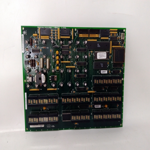
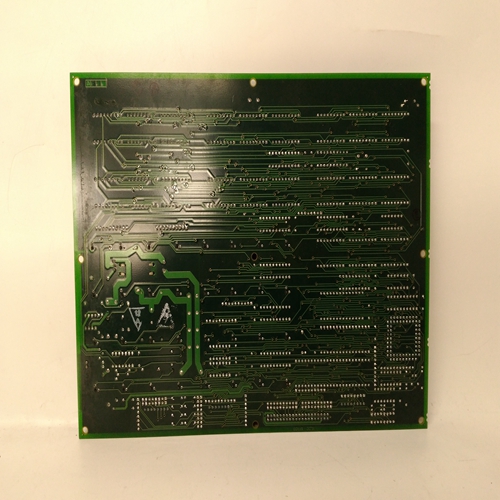
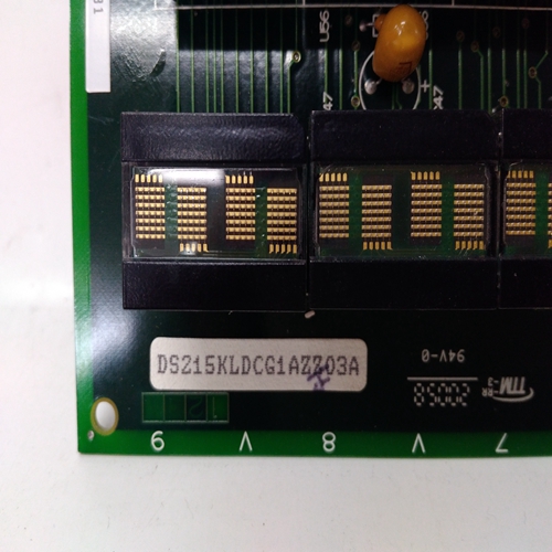
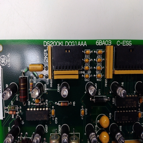
DS200KLDCG1AAA燃機輸出模塊
按鈕循環數據占用兩個LIL通道。在ODP配置期間輸入起始信道
每個回路的操作員顯示功能塊,如LIL CHAN(n)。每個循環的第一個通道可以在中查看
從信道7/參數38開始的站數據。站配置條目(基于本地和圖形PC)將指示六個相鄰信道的下一可用開放空間。可以輸入另一個起始頻道,但重要的是利用最低的信道總數。
下表中的信道位置n到n+1確定了LIL上每個信道的可用變量模擬指示器回路。所有參數1數據(例如離散輸入狀態)均為全局數據,每0.5秒傳輸一次。
所有其他數據按命令發送。
數據映射
本節提供Modbus、本地儀表鏈路和以太網的回路和站數據映射。Modbus是標準LIL和以太網選項板可用,必須安裝正確的板才能啟用任一選項通信協議。通過Ethernet選項,使用嵌入在TCP協議。這在業界被稱為開放式Modbus/TCP協議。控制器有一個RS232端口,始終通過Modbus通信。它位于操作員面板。
每個控制器還具有一個多點網絡連接,即Modbus、LIL(當可選的LIL板安裝)或以太網(當安裝可選以太網板時)。以太網連接使用標準RJ45連接器。網絡可以互連:
?Procidia i|pac、Moore 352Plus、Moore353和Moore-354N控制器以及運行I124Ware PC的計算機?,過程套件?, 米克羅優勢? 或其他操作員界面軟件,包括控制器中的通信驅動程序(例如Modbus、LIL(320)或OPC以太網)。
?Procidia i |pac、Moore 352Plus、Moore353和Moore354N控制器以及APACS?39ACM型
通過Modbus或LIL的高級控制模塊
網絡允許數據從工作站上傳到計算機或工作站。通常使用該數據用于過程和報警監控,對庫存管理和會計數據進行額外處理,以及工藝和設備故障排除。可以將數據下載到站以改變設定點或閥值,更改控制模式,并確認報警。與配置、上傳/下載相關的專有數據傳輸或與
i |config圖形配置實用程序沒有描述。MPU控制器固件版本標識為:如前幾節所述。
7.1連接到APACS 39ACM、MYCROADVANTAGE、ProcessSuite、i|ware PC
7.1.1亞太地區
39ACM型(高級控制模塊)支持Modbus和LIL連接。使用標準
Modbus主功能塊庫,用于與工作站通信。請求Modbus數據時,不要
每個請求超過48個線圈或60個寄存器。LIL功能塊庫(P/N 15939-625V4.00 ACM系列通信FB庫LIL)提供了將ACM連接到標準LIL站的方法
可獲得的該庫包括Moore 352P/353/354環路塊。庫的當前版本映射
352P/353/354具有位于通道8、13和18的3個環路。因此,有必要配置ODC
這些通道的功能塊。預計該庫的后續版本將允許多個循環,最多
允許的最大值。此外,還可以通過使用其他庫的組合來獲得來自其他循環的數據
函數,如LIL_GBL、LIL_ NGBL和LILUCMD。
Pushbutton loop data occupies two LIL channels. The starting channel is entered during configuration of the ODP
operator display function block for each loop, as LIL CHAN (n). The first channel for each loop can be viewed in
station data starting at channel 7/parameter 38. The station configuration entry (both local and graphical PC-based)
will indicate the next available open space of six contiguous channels. Another starting channel can be entered but
it is important to utilize the lowest total number of channels.
Channel locations n through n+1, in the table below, identify variables that will be available on the LIL for each
analog indicator loop. All parameter 1 data (e.g. discrete input states) is global and is transmitted every 0.5 second.
All other data is sent out on command. DATA MAPPING
This section provides loop and station data mapping for Modbus, Local Instrument Link, and Ethernet. Modbus is
standard. LIL and Ethernet option boards are available and the correct board must be installed to enable either
communication protocol. With the Ethernet option, data is accessed using Modbus commands embedded within the
TCP protocol. This is becoming known within the industry as the Open Modbus/TCP Protocol.
The controller has an RS232 port that always communicates via Modbus. It is located on the underside of the
operator faceplate.
Each controller also has a multi-drop network connection that is either Modbus, LIL (when the optional LIL board
is installed), or Ethernet (when the optional Ethernet board is installed). The Ethernet connection is made using the
standard RJ45 connector. The network can interconnect:
? Procidia i|pac, Moore 352Plus, Moore 353 and Moore 354N Controllers and a computer running i|ware PC?,
ProcessSuite?, MYCROADVANTAGE? or other operator interface software that includes the
communication driver (e.g. Modbus, LIL (320), or OPC Ethernet) in the controller.
? Procidia i|pac, Moore 352Plus, Moore 353 and Moore 354N Controllers and an APACS? Model 39ACM
Advanced Control Module via Modbus or LIL
The network permits data to be uploaded from the station to the computer or workstation. This data is typically used
for process and alarm monitoring, additional processing of the data for inventory management and accounting, and
process and equipment troubleshooting. Data can be downloaded to the station to change setpoint or valve value,
change control mode, and acknowledge alarms.
Proprietary data transfers associated with configuration upload/download or on-line monitoring associated with the
i|config Graphical Configuration Utility are not described. MPU Controller firmware versions are identified as
explained in earlier sections.
7.1 CONNECTING TO APACS 39ACM, MYCROADVANTAGE, ProcessSuite, i|ware PC
7.1.1 APACS
A Model 39ACM (Advanced Control Module) supports both Modbus and LIL connections. Use the standard
Modbus Master Function Block Library to communicate with a station. When requesting Modbus data, do not
exceed 48 coils or 60 registers per request. A LIL function block library (P/N 15939-625V4.00 ACM Serial
Communication FB Library LIL) that provides a method for connecting the ACM to standard LIL stations is
available. The library includes a Moore 352P/353/354 Loop block. The current release of the library maps the
352P/353/354 as having 3-loops located at channels 8, 13, and 18. Therefore, it is necessary to configure ODC
function blocks for these channels. It is expected that later releases of the library will allow multiple loops, up to
maximum allowed. Also, data from additional loops can be obtained by using a combination of other library
functions such as LIL_GBL, LIL_NGBL, and LIL_CMD.


