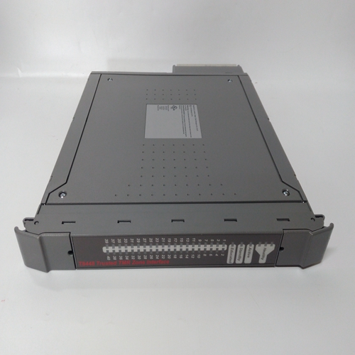
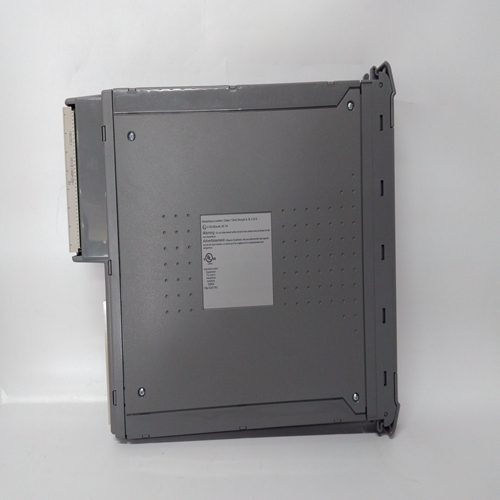
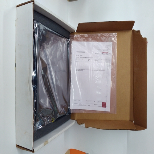
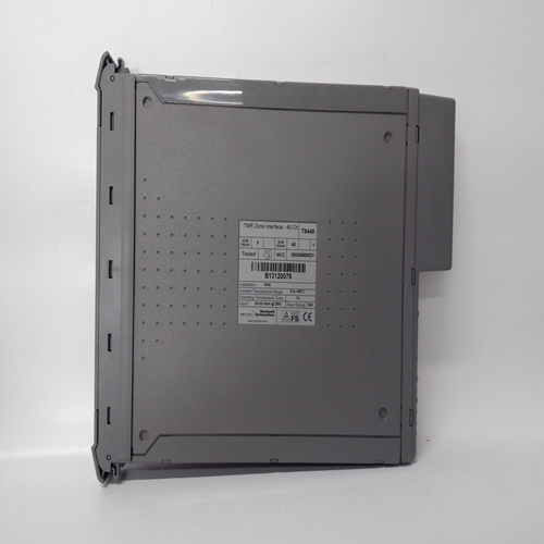
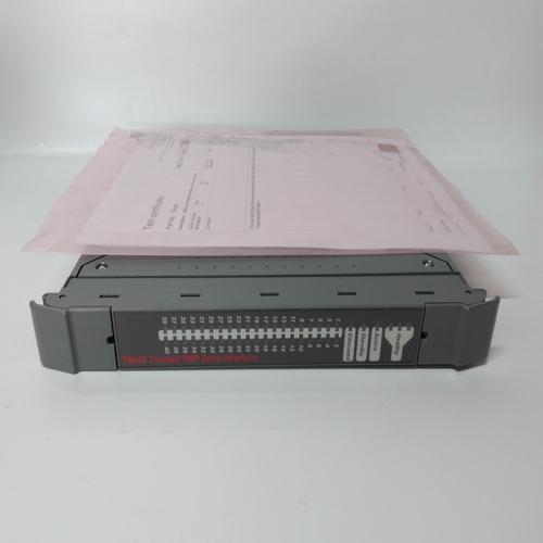
ICS TRIPLEX T8448控制器模塊
ODA塊是one上使用的五個操作員顯示器之一按回路配置本地操作員顯示功能,以及網絡參數。請參閱下一頁的i|ware PC面板。該塊將顯示最多四個過程變量P1至P4模擬條形圖和數字形式。兩個報警與每個過程變量。它們可以配置為高或低報警。每個報警功能具有高(1)的相關塊輸出當警報激活時。當發生循環事件時,輸出LE為高(1)是活動的。當站錯誤激活時,輸出SE為高。循環#參數用于索引對Modbus和LIL的讀取和寫入網絡參數。網絡參數見第6節和第7節。視圖OD參數設置為“是”時,啟用操作員要在本地查看和訪問的顯示。如果它在希望僅從網絡查看顯示或操作參數工作站,參數應設置為“否”。
所有四個過程輸入的范圍指針(即R1到R4)必須為:被配置為定義每個變量輸入的范圍(即P1到P4)。
如果未配置這些參數,將縮放條形圖使用0.00到100.00的工程范圍
此信息也定義提供給遠程的循環信息的比例網絡上的工作站(即Modbus或LIL)。每個過程變量可通過以下方式顯示在本地面板上:D按鈕。當第一次使用循環按鈕進入循環時,將顯示回路標簽(如AnDisp1)。然而,如果存在循環中具有未確認報警的點,該點將在點標記和報警之間交替顯示條件(例如PI693/3B LO)。按D按鈕滾動瀏覽在中顯示點標簽(例如TI712)的模擬點數字顯示中的字母數字和點的值(例如。348.47). 按“單位”按鈕顯示點的單位。按循環標記返回顯示循環標記。
報警類型HI將過程輸入與極限設置進行比較,并使報警狀態高(1),當進程等于或高于限制設置。當進程較少時,報警狀態將清除(0)大于極限設置減去死區。LO將過程輸入與極限設置進行比較,并使當進程等于或小于限制設置。當流程處于以下狀態時,報警狀態將清除(0):大于極限設置加上死區。
或將過程輸入與引用的范圍限制進行比較范圍指針參數。它將觸發報警狀態高(1)
當過程等于或大于上限時,或等于達到或低于下限。當進程小于上限減去死區或更大高于下限加上死區。
ODA blocks are one of five operator displays that are used on a one
per loop basis to configure the local operator display functions and
network parameters. See the i|ware PC faceplate on the next page.
The block will display up to four process variables P1 to P4 in both
analog bargraph and digital form. Two alarms are associated with
each process variable. They can be configured as HI or LO alarms.
Each alarm function has associated block outputs that are high (1)
when the alarm is active. Output LE is high (1) when a loop event
is active. Output SE is high when a station error is active. LOOP #
parameters are used to index reads and writes to Modbus and LIL
network parameters. See Sections 6 and 7 for network parameters.
The VIEW OD parameter, when set to YES, enables the operator
display to be viewed and accessed locally. In cases where it is
desired to view display or operation parameters only from a network
workstation, the parameter should be set to NO.
Range pointers (i.e. R1 to R4) for all four process inputs must be
configured to define the range of each variable input (i.e. P1 to P4).
If these parameters are not configured, the bargraphs will be scaled
using the engineering range of 0.00 to 100.00. This information also
defines the scaling of the loop information provided to a remote
workstation over the network (i.e. Modbus or LIL).
Each process variable can be displayed on the local faceplate using
the D button. When first stepping into a loop using the Loop button,
the loop tag will be displayed (e.g. AnDisp1). However, if there is a
point within the loop that has an unacknowledged alarm, that point
will be displayed alternating between the point tag and the alarm
condition (e.g. PI693/3B LO). Press the D button to scroll through
the analog points displaying the point tag (e.g. TI712) in the
alphanumeric and the value of the point in the digital display (e.g.
348.47). Press the UNITS button to display the units of the point.
Press the Loop tag to return to displaying the loop tag.
Alarm Types
HI compares the process input with the limit setting and trips the
alarm status high (1) when the process is equal to or higher than the
limit setting. The alarm status will clear (0) when the process is less
than the limit setting minus the deadband.
LO compares the process input with the limit setting and trips the
alarm status high (1) when the process is equal to or less than the
limit setting. The alarm status will clear (0) when the process is
greater than the limit setting plus the deadband.
OR compares the process input with the range limits referenced by
the range pointer parameter. It will trip the alarm status high (1)
when the process is equal to or greater than the high limit, or equal
to or less than the low limit. The alarm status will clear (0) when the
process is less than the high limit minus the deadband or greater
than the low limit plus the deadband.


