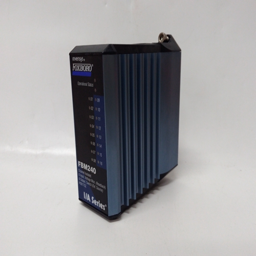
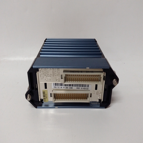
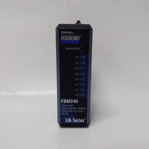
FBM240冗余8通道模塊
通電-在熱啟動或熱啟動期間,當PU最后設置為“是”時,塊將初始化為輸入/輸出狀態和斷電瞬間有效的運行時間。冷啟動,PU最后設置為否,將輸入/輸出狀態和運行時間初始化為0。E/I功能塊可用于每個循環一個
選擇模擬信號的基礎,連接到輸入E(外部)或輸入I(內部),作為環路控制器。
E/I開關的位置可以在每個開關上改變輸入ST和的正轉換通常為連接至按鈕塊的PS輸出PB2SW,配置用于瞬時動作。SE輸出通常連接到的MD輸入按鈕塊PB2SW。E/I開關位置將為:
操作員面板上由發光的LED顯示:綠色代表E,紅色代表I。
E/I開關位置也可以通過以下方式改變:通過Modbus或LIL網絡的命令。
當PU LAST設置為YES時,E/I開關將在熱天氣或暖天氣期間,在最后一個位置通電
開始在冷啟動期間,它將在通電參數設置的位置。如果最后一個PU設置為“否”,E/I開關將在最后一個中通電熱啟動期間的位置,但在熱啟動或冷啟動期間,
將在通電設置的位置通電參數IO(內部超馳)輸入啟用HI(1)輸入
以臨時選擇內部輸入作為功能塊輸出O1。該輸入不影響E/I開關的位置。輸出SE和SI指示E/I開關的實際位置。SE在E位置時為高(1),在低(0)時為低當處于I位置時。SI在I位置時為HI,在E位置時為LO。輸出IS和ES指示:塊輸出的實際源。當O1為內部輸入時,IS為高,當O1是外部輸入時,為低輸入當O1是外部輸入時,ES為高電平,當O1為內部輸入時ES為低電平。固件1.30及更高版本中的ESL功能塊可以是在每個循環一次的基礎上用于記錄循環內的事件。
每個ESL輸入可以分配一個用戶標記(最多8個ASCII字符),當查看記錄的
來自前面板的事件。事件,一旦由正向轉換0>1輸入,將保留在記錄儀中直到復位。可通過設置輸入R啟動復位高(此輸入對邊緣敏感,將重置事件在前緣)或通過輸入配置和將參數重置設置為“是”。
POWER UP - During a warm or a hot start, with PU LAST set to YES, the block will initialize with the
input/output states and elapsed time in effect at the instant power down occurred. A cold start, with PU LAST set to
NO, will initialize the input/output states and elapsed time to 0. E/I function blocks can be used on a one per loop
basis to select an analog signal, connected to input E
(External) or input I (Internal), as a setpoint for the
loop controller.
The position of the E/I switch can be changed on each
positive transition of input ST and will normally be
connected to the PS output of pushbutton block
PB2SW, configured for momentary action. The SE
output will normally be connected to the MD input of
pushbutton block PB2SW. E/I switch position will be
shown on the operator faceplate by a lighted LED:
green for E, red for I.
The E/I switch position can also be changed by
command over the Modbus or LIL network.
When PU LAST is set to YES, the E/I switch will
power up in the last position during a hot or a warm
start. During a cold start, it will power up in the
position set by the POWER UP parameter. If PU LAST is set to NO, the E/I switch will power up in the last
position during a hot start, but during a warm or cold start will power up in the position set by the POWER UP
parameter.
The IO (Internal Override) input enables a HI (1) input to temporarily select the Internal Input as the function block
output O1. This input does not affect the position of the E/I switch.
Outputs SE and SI indicate the actual position of the E/I switch. SE is HI (1) when in the E position and LO (0)
when in the I position. SI is HI when in the I position and LO when in the E position. Outputs IS and ES indicate
the actual source of the block output. IS is HI when O1 is the Internal input and is LO when O1 is the External
input. ES is HI when O1 is the External input and is LO when O1 is the Internal input.ESL function blocks, in firmware 1.30 and higher, can be
used on a one per loop basis to log events within the loop.
Each ESL input can be assigned a user tag (up to 8 ASCII
characters) that will be displayed when viewing the logged
events from the front panel. Events, once triggered by a
positive transition 0>1 input, will remain in the logger
until reset. Reset can be initiated either by setting input R
high (this input is edge sensitive and will reset the events
on the leading edge) or by entering configuration and
setting the parameter RESET to YES.


