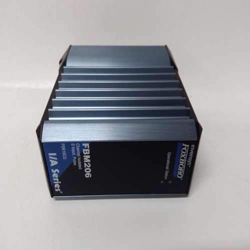
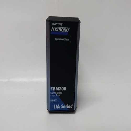
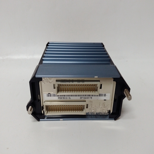
P0916CQ脈沖輸入模塊
DOD_功能塊最多傳輸16個開/關信號從控制器塊互連接收到遠程LonWorks網(wǎng)絡上的節(jié)點。最大6 DOD可以使用塊,但不超過上允許的節(jié)點數(shù)Lon網(wǎng)絡或控制器的內存限制。
每個區(qū)塊的使用都將分配一個唯一的樁號寬ID(如DOD01)。傳輸?shù)拿總€輸入類型為:SNVT_lev_disc,可以綁定到中的網(wǎng)絡變量可以接收網(wǎng)絡的單個或多個遠程節(jié)點此類型的變量。這些區(qū)塊將在以下情況下可用:
LonWorks選項板安裝在352P、353或354N控制器。0 NV NUM參數(shù)啟用工作站分配給輸入0的編號
查看。
所有后續(xù)網(wǎng)絡變量均已分配連續(xù)地。
每個功能塊輸入具有與其關聯(lián)的模式。模式可以是正常模式或強制模式。什么時候使用能夠發(fā)送LIL或Modbus命令的PC,模式可以改變,強制狀態(tài)可以改變分配高(1)或低(0)值。價值觀兩個輸入(F和N)可通過網(wǎng)絡訪問以及SPDT開關的位置,如框圖。“0”模式正常,“1”模式正常強迫。每個功能塊輸入還具有相關的質量狀態(tài)用它。當模塊確定時,該狀態(tài)將變?yōu)楦撸?)它已與綁定到該節(jié)點的Lon節(jié)點失去通信
輸入如果任何單個質量輸入較高,則質量狀態(tài)塊輸出也將很高。DOE_功能塊在以下情況下可用:安裝了以太網(wǎng)通信板。最多32個DOE塊可用,并按順序分配給每個塊使用,全站性。最多可配置16個數(shù)字輸入。該區(qū)塊將將輸入I0-IF打包為單個整數(shù)字,該整數(shù)字可以是從另一個具有以太網(wǎng)的控制器訪問通信能力。
每個DOE塊自動分配Modbus可以從任何具有Modbus以太網(wǎng)功能。當可選的LIL時,DOL_功能塊可用已安裝通信板。他們允許車站:輸出全局字GW,其中位0-F表示狀態(tài)每個布爾輸入D0-DF的1或0。未配置輸入設置為0。DOL塊編號在每次使用的順序,全站范圍。
2DOD_ function blocks transmit up to 16 on/off signals
received from a controller block interconnection to remote
nodes on the LonWorks network. A maximum of 6 DOD
blocks can be used, up to the limit of nodes allowed on
the Lon network or the memory limit of the controller.
Each use of the block will be assigned a unique station
wide ID (e.g. DOD01). Each input transmitted is of type
SNVT_lev_disc and can be bound to network variables in
a single or multiple remote nodes that can receive network
variables of this type. These blocks will be available when
the LonWorks option board is installed in a 352P, 353, or
354N controller. The 0 NV NUM parameter enables the
number that the station has assigned to input 0 to be
viewed. All subsequent network variables are assigned
consecutively.
Each function block input has a mode associated with it.
The mode can be either NORMAL or FORCED. When
using a PC capable of sending LIL or Modbus commands,
the mode can be changed and the forced state can be
assigned a high (1) or low (0) value. The values
accessible over the network are the two inputs (F and N)
and the position of the SPDT switch illustrated in the
block diagram. A mode of ‘0’ is Normal and ‘1’ is
Forced. Each function block input also has a quality status associated
with it. This status will go high (1) when the block determines
it has lost communication with the Lon node bound to that
input. If any of the individual quality inputs are high, the
Quality Status block output will also be high. DOE_ function blocks are available when the optional
Ethernet communication board is installed. Up to 32 DOE
blocks are available and are assigned in sequence with each
use, station wide.
Up to 16 digital inputs can be configured. The block will
pack inputs I0 - IF into a single integer word which can be
accessed from another controller having Ethernet
communication capability.
Each DOE block is automatically assigned Modbus
registers that can be accessed from any device having the
Modbus Ethernet capability. DOL_ function blocks are available when the optional LIL
communication board is installed. They allow the station to
output a global word GW with bits 0-F representing the state
1 or 0 of each of the Boolean inputs D0 - DF. Unconfigured
inputs are set to 0. DOL block numbers are assigned in
sequence with each use, station wide.


