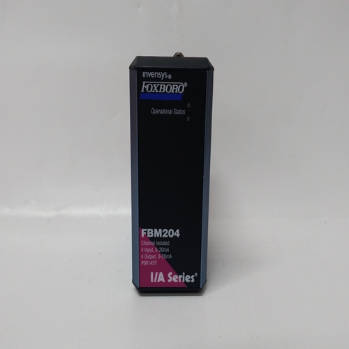
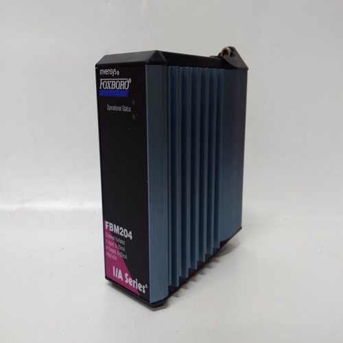
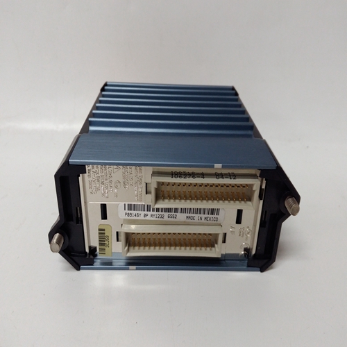
P0914SY電流輸入模塊
I/O擴展器板上有兩個DINU_塊。
這些塊及其終端的固定名稱(ID)第8.4節列出了名稱。
輸出CT表示縮放的(實際計數x K)總數:
上次復位后出現的輸入脈沖。此輸出是實數,并可用于多種應用,例如直接計數輸入到BAT批次累加器
函數塊或數學運算中,例如計算比率微調電路中計數之間的差異。
Output IS是輸入的當前狀態
塊在每個控制器掃描周期開始時執行。它輸入為低時將為低(0),輸入為高時將為高(1)輸入高。
輸出SF是一個縮放頻率(使用FREQ MIN和MAX參數),可以表示流速、速度或
具有頻率信號的其他發射機變量
當FREQ MAX參數設置為25或更小時,20使用msec接觸去抖動。
當使用觸點去抖動時,脈沖輸入必須保持開啟20毫秒才能
被識別為有效脈沖。輸出SF與頻率呈線性關系,可使用CHR函數進行表征
如有必要,請阻止。使用MINSCALE、MAXSCALE和MAXSCAL將工程范圍和單位分配給該信號,
DPP和ENGUNITS參數。它們可用于使用OR輸出連接的其他塊。
輸入R將輸出CT重置為0.0。輸入D控制計數方向。當方向輸入D為低(0)時
計數將向后移動,包括負值。方向輸入功能允許使用倒計時
計數器,它允許復制以前的計算機脈沖接口執行的功能
脈沖/方向格式。輸入TC斷言高電平(1)將強制縮放計數跟蹤外部信號。這可以用于CT輸出用于設置值(例如設定點)的應用,該值可從另一個來源。
質量狀態輸出QS指示塊輸出的質量高(1)
當輸出CT、IS或SF為壞時質量質量差表示在硬件轉換電路。
通電-在PU最后設置為“是”的情況下CT輸出將在最后一個值上電在熱啟動或熱啟動期間。如果設置為否,在熱啟動或冷啟動期間,它將設置為0.0。在熱啟動、熱啟動或冷啟動期間,數字濾波器將被臨時旁路。
Two DINU_ blocks are available on the I/O expander board.
The fixed names (IDs) of these blocks and their terminal
designations are listed in Section 8.4.
Output CT represents the scaled (actual count x K) total of
input pulses that occurred since the last reset. This output is a
real number and can be used in a number of applications,
such as a direct count input to the BAT batch totalizer
function block or in math operations, such as computing the
difference between counts in a ratio trim circuit.
Output IS is the current state of the input at the time the
block is executed at the start of each controller scan cycle. It
will be low (0) when the input is low and high (1) when the
input is high.
Output SF is a scaled frequency (using the FREQ MIN and MAX parameters) that can represent flow rate, speed, or
other transmitter variable that has a frequency signal. When the FREQ MAX parameter is set to 25 or less, a 20
msec contact debounce is used. When contact debounce is used, a pulse input must remain on for 20 msec to be
recognized as a valid pulse. Output SF is linear with frequency and can be characterized using the CHR function
block if necessary. An engineering range and units are assigned to this signal using the MINSCALE, MAXSCALE,
DPP, and ENGUNITS parameters. They are available to other blocks using the OR output connection.
Input R resets output CT to 0.0. Input D controls the direction of the count. When direction input D is low (0), the
count will move backwards, including negative values. The direction input feature enables the use of count down
counters and it allows duplication of functions performed by previous computer pulse interfaces having a
Pulse/Direction format. Input TC asserted high (1) will force the scaled count to track an external signal. This can
be used in applications where the CT output is being used to set a value (e.g. setpoint) that can be changed from
another source.
The quality status output QS indicates the
quality of the block outputs and is high (1)
when outputs CT, IS, or SF are of bad
quality. Bad quality indicates a failure in the
hardware conversion circuit.
POWER UP - With PU LAST set to YES, the
CT output will power up at the last value
during a hot or warm start. If set to NO,
during a warm or a cold start, it will be set to
0.0. The digital filter will be temporarily bypassed during a hot, a warm or a cold start.


