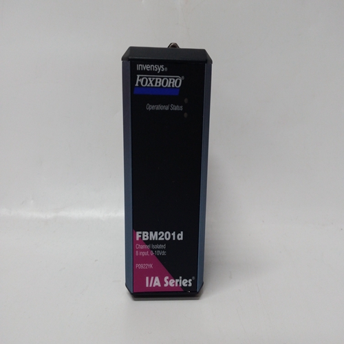
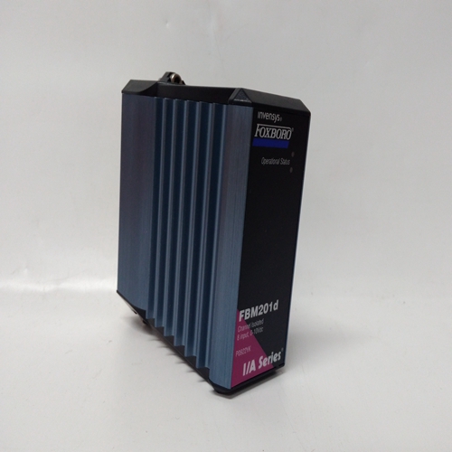
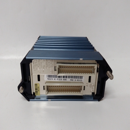
P0922YK輸入模塊
功能塊還可以提供脈沖輸出以驅動遠程計數器。脈沖輸出功能集成輸入信號使用相同的時基和輸出脈沖,其速率由PUL SCAL配置確定參數該參數確定了必須發生的積分器總值的變化,以產生新的輸出脈沖。
在上述示例中,如果PUL SCAL等于10,則在同一時間段內將發生總共30個脈沖。這個PUL SCAL值也是用于將加侖的精確值讀取到遠程計數器的乘數。脈沖輸出功能對模擬輸入的絕對值進行操作。無論是負還是正值要被累加,比較器塊可用于感測模擬輸入和CMP的極性然后,輸出可以向計數器指示方向。確保PUL SCAL設置不需要大于的掃描周期時間的脈沖率輸出最大輸入條件下的控制器。使用相同的示例,如果最大A輸入為60.0循環時間為0.1秒,最大所需脈沖速率為0.1/秒。由于最大輸出要求小于0.1秒循環時間下可用的最大脈沖速率5/秒,因此滿足該條件。這個如果選擇的脈沖標度為1,也將滿足要求,這將需要最大脈沖速率為1/秒。
通電-在熱啟動期間,如果配置參數PU LAST設置為YES,則積分器功能將使用斷電前的最后一個值初始化,所有輸出將初始化為斷電前的最終值斷電。如果設置為“否”,或在冷啟動期間,積分器和所有輸出將初始化為0。輸入EC允許批量累加器塊與另一個功能塊一起使用,例如提供計數信號。
輸入A未配置時,將設置為(0.0)。
EC輸入與初始值相加用作總數。該值現在將在操作員面板上顯示為總計,預設值將起作用在此值上提供輸出A1和A2。BATSW功能塊可用于每個循環一個原因每個都與PID功能塊一起使用,以消除:啟動條件下的超調。當放置在控制器的反饋路徑:導致復位要減少的控制器組件(如果是控制器動作為Rev)。在以下過程中不使用批處理開關:啟動時,控制器輸出(O1=GE+R)將等于復位后的全輸出將結束。這需要超調設定點的過程,以使控制器輸出下降。在反饋路徑,當出現以下情況時,將出現較低的重置值發生交叉,從而減少或消除過沖。
The function block can also provide a pulse output to drive a remote counter. The pulse output function integrates
the input signal using the same time base and output pulses at a rate determined by the PUL SCAL configuration
parameter. This parameter determines the change to the integrator total that must occur to cause a new output pulse.
In the above example, if PUL SCAL equals 10, a total of 30 pulses will have occurred in the same time period. The
PUL SCAL value is also the multiplier that would be used to read the exact value of gallons to a remote counter.
The pulse output function operates on the absolute value of the analog input. When both negative and positive
values are to be totalized, a CoMParator block can be used to sense the polarity of the analog input and the CMP
output can then indicate a direction to the counter.
Be sure that the PUL SCAL setting does not require a pulse rate output greater than the scan cycle time of the
controller under the maximum input conditions. Using the same example, if the maximum A input is 60.0 and the
cycle time is 0.1 sec, the maximum required pulse rate is 0.1/sec. The condition is satisfied since the maximum output requirement is less than the maximum pulse rate of 5/sec available with a 0.1 sec cycle time. The
requirement would also be satisfied if a PUL SCAL of 1 was selected which would have required a maximum pulse
rate of 1/sec.
POWER UP - During a warm start, if the configuration parameter PU LAST was set to YES, the integrator function
will initialize with the last value prior to power down and all outputs will be initialized to the last value prior to
power down. If set to NO, or during a cold start, the integrator and all outputs will initialize to 0.
Input EC allows the batch totalizer block to be used with another function block, such as the DINU that provides a
count signal. When input A is not configured it will be set to (0.0). The EC input is summed with the initial value
for use as the total. This value will now be displayed as the total on the operator faceplate and the presets will act
on this value to provide outputs A1 and A2. BATSW function blocks can be used on a one per loop
basis. Each is used with a PID function block to eliminate
overshoot during startup conditions. When placed in the
feedback path of the controller it causes the reset
component of the controller to be reduced (if controller
action is Rev). Without the use of a batch switch during
startup, the controller output (O1 = GE + R) will equal
full output since the reset will wind up. This requires the
process to overshoot the setpoint in order to bring the
controller output back down. With a batch switch in the
feedback path, a lower reset value will be present when
crossover occurs, thus reducing or eliminating overshoot.


