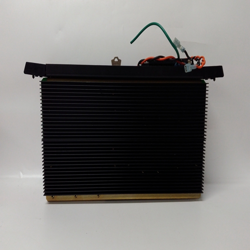
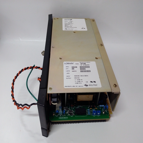
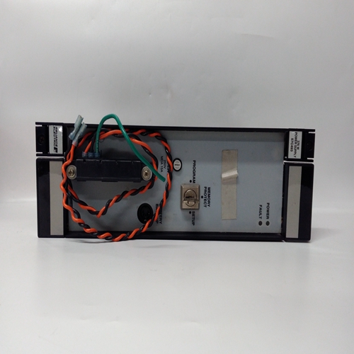
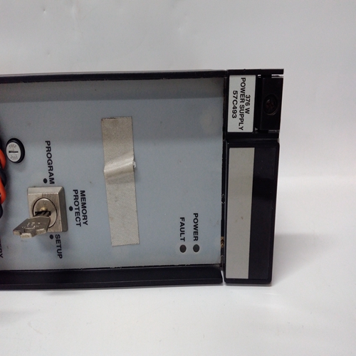
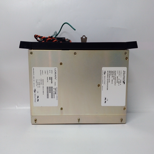
RELIANCE 57C493自動(dòng)化模塊
AOUT_功能塊轉(zhuǎn)換功能塊互連信號(hào),連接到輸入S,連接到a具有范圍為4-20 mAdc的塊輸出。輸入D可用于斷開輸出與斷言為高(1)時(shí)的負(fù)載。此功能非常有用當(dāng)兩個(gè)或多個(gè)控制器連接到公共負(fù)載。當(dāng)一個(gè)控制器連接到使用斷開功能。功能塊包括:通過塊縮放至4-20 mA輸出范圍輸入信號(hào)。范圍指針參數(shù)(輸入R)告訴塊從何處獲取縮放信息。
如果未配置此參數(shù),則塊將:使用0.00到100.00的范圍。上有兩個(gè)模擬輸出功能塊:
控制器板和擴(kuò)展器板。功能塊名稱和終端標(biāo)識(shí)如下所示。輸出是工廠的校準(zhǔn)為4-20 mAdc,不需要現(xiàn)場(chǎng)校準(zhǔn)。但是,如果出現(xiàn)以下情況,可以進(jìn)行現(xiàn)場(chǎng)校準(zhǔn)渴望的通過調(diào)整脈沖發(fā)生器校準(zhǔn)輸出,直到獲得所需輸出(即,0為4.0 mA)然后按下存儲(chǔ)按鈕。校準(zhǔn)期間,驗(yàn)證模式可用,將在中顯示mA值數(shù)字顯示,脈沖發(fā)生器在整個(gè)范圍內(nèi)調(diào)整輸出。
輸出QS是質(zhì)量狀態(tài)輸出
如果輸出驅(qū)動(dòng)器檢測(cè)到高阻抗或開路,它將變高環(huán)行字母數(shù)字將閃爍AOUT_。當(dāng)檢測(cè)到開路情況時(shí)為OC。QS輸出可以也可用于在冗余應(yīng)用中切換到第二輸出電路。固件1.30及更高版本中的ATD_塊可用作在循環(huán)中需要(每個(gè)循環(huán)最多5個(gè)),以趨勢(shì)連接到輸入A的模擬變量。塊可以存儲(chǔ)最多170個(gè)數(shù)據(jù)點(diǎn),具體取決于啟用/禁用功能(見下文)。趨勢(shì)可能是使用Modbus命令顯示。可以檢索數(shù)據(jù)并由遠(yuǎn)程操作員站顯示,并顯示來自該站的數(shù)據(jù)分組。個(gè)人電腦或運(yùn)行i|ware PC操作員界面軟件的I124Station可以在回路詳細(xì)信息屏幕或模擬詳細(xì)信息上顯示趨勢(shì)數(shù)據(jù)屏幕參數(shù)TRND TYP允許將數(shù)據(jù)存儲(chǔ)在兩種格式:每個(gè)采樣時(shí)間的平均值或每個(gè)采樣時(shí)間內(nèi)數(shù)據(jù)的峰值/峰值。全部的基于RG PTR(范圍指針)輸入。范圍信息將:在通過網(wǎng)絡(luò)檢索時(shí)成為數(shù)據(jù)包的一部分通信。未配置此輸入時(shí),范圍將使用0.0-100.0。
AOUT_ function blocks convert function block
interconnection signals, connected to input S, to a
block output having a range of 4-20 mAdc. Input
D can be used to disconnect the output from the
load when asserted high (1). This feature is useful
when two or more controllers are connected to a
common load. When one controller is connected to
the load, others are disconnected using the
disconnect feature. The function block includes
scaling to range the 4-20 mA output with the block
input signal. The range pointer parameter (input R)
tells the block where to obtain scaling information.
If this parameter is not configured the block will
use a range of 0.00 to 100.00.
Two analog output function blocks are available on
the Controller Board and one additional on the
Expander Board. Function block names and terminal identifications are listed below. The output is factory
calibrated for 4-20 mAdc and should not require field calibration. However, field calibration can be performed if
desired. The output is calibrated by adjusting the pulser until the desired output (i.e. 4.0 mA for zero) is obtained
and then pressing the store button. A verify mode is available during calibration that will show the mA value in the
numeric display as the pulser adjusts the output over the full range.
Output QS is the Quality Status output. It will go high if the output driver detects a high impedance or an open
circuit. The alphanumeric will flash AOUT_.OC when an open circuit condition is detected. The QS output could
also be used to switch to a second output circuit in a redundancy application. ATD_ blocks, in firmware 1.30 and higher, can be used as
needed in loops (up to a maximum of 5 per loop) to trend an
analog variable connected to input A. The block can store
up to 170 data points depending upon the use of the
enable/disable function (see below). A trend can be
displayed using Modbus commands. Data can be retrieved
and displayed by a remote operator station that can retrieve,
interpret, and display data packets from the station. A PC or
i|station running i|ware PC operator interface software can
display trend data on a Loop Detail screen or Analog Detail
screen.
Parameter TRND TYP allows data to be stored in one of
two formats: the average over each sample time or the
peak/peak values of the data over each sample time. All
data is stored in a normalized form based on the value of the
RG PTR (range pointer) input. The range information will
be part of the data packet when retrieved over the network
communications. When this input is unconfigured, a range
of 0.0 - 100.0 will be used.


