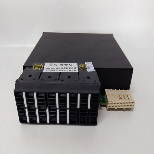
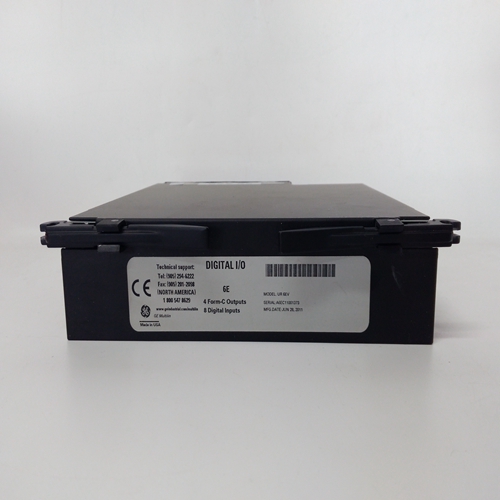
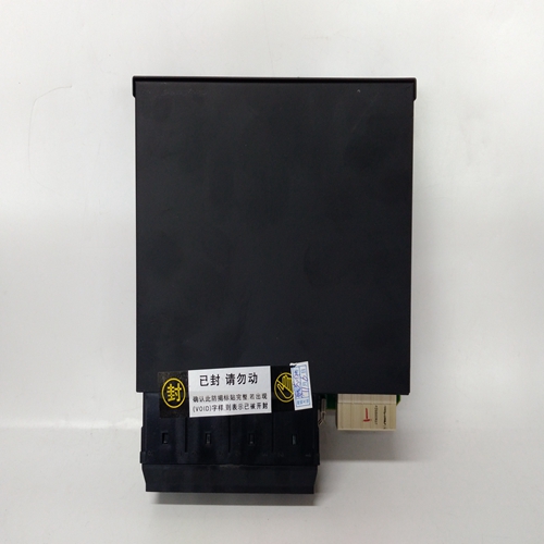
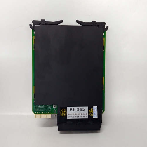
UR6EV綜合保護繼電模塊
啟動程序在此之前,應詳細檢查系統(tǒng)接線啟動程序。
按如下方式啟動系統(tǒng):
(1) 確保系統(tǒng)電源已關閉。
(2) 通過以下方式斷開與直流輸入卡的電源連接:拆下兩件式連接器TB1。拆下接線盒TB2如果使用的話。
(3) 擰下用于固定控制卡的兩個固定螺釘然后,使用提取工具,從使機架之間沒有電氣連接控制卡和背板。
4) 打開系統(tǒng)電源。
(5) 檢查是否存在18V和32V直流電壓之間的電壓接線盒TB1。通過檢查
催化傳感器的磁珠mA和mV信號或mA信號
對于4-20mA傳感器。
(15) 對中的其余控制卡重復步驟(11)至(14)支架
(16) 將接線盒TB2重新連接到直流輸入卡,并測試可選工程卡模塊,符合相關操作手冊說明。
(17) 使用繼電器測試驗證每個通道的報警配置第7章第6節(jié)概述的程序。
(18) 驗證系統(tǒng)57控制卡和電源是否正常在最高規(guī)定工作溫度下工作溫度為55℃。
校準讓連接的傳感器穩(wěn)定一段適當?shù)臅r間,如下所示:傳感器手冊中規(guī)定。
調整催化傳感器的傳感器頭電流,如中所述第7章第7節(jié)至傳感器中指示的所需值操作說明。
使用所用傳感器類型的程序,遵循第7章第8節(jié)和第10節(jié)中的零量程和第一量程操作指南,并校準每個通道。
維護為確保系統(tǒng)正常運行,應進行以下維護:根據(jù)現(xiàn)場規(guī)定定期進行,以及所用傳感器類型的說明。對于安裝在應遵循歐盟EN 50073。
START UP PROCEDURE
A detailed check of the system wiring should be carried out prior to this
start-up procedure.
Start-up the system as follows:
(1) Ensure that the system power supply is switched off.
(2) Disconnect the power supply connections to the DC Input Card by
removing the two part connector TB1. Remove terminal block TB2
if used.
(3) Unscrew the two retaining screws used to secure the control cards
and then, using the extraction tool, partially remove the cards from
the rack so that there is no electrical connection between the
control cards and the backplane.
(4) Switch on the system power supply.
(5) Check that a voltage of between 18V and 32V dc exists at the
terminal block TB1.
Check the operation of the connected sensor by checking the
BEAD mA and mV SIGNAL for a catalytic sensor or the mA SIGNAL
for a 4 - 20mA sensor.
(15) Repeat Steps (11) to (14) for the remaining control cards in the
rack.
(16) Reconnect the terminal block TB2 to the DC Input Card and test the
optional Engineering Card module in accordance with the relevant
operating manual instructions.
(17) Verify the alarm configuration for each channel using the relay test
procedure outlined in Chapter 7 Section 6.
(18) Verify that the System 57 Control Cards and power supply are
operating within the maximum specified operating temperature
of 55 C.
CALIBRATION
Leave the connected sensors to stabilise for a suitable period as
specified in the sensor manual.
Adjust the sensor head current of catalytic sensors as described in
Chapter 7 Section 7 to the required value as indicated in the sensor
operating instructions.
Using the procedures for the type of sensors being used, follow the
zero and 1st span operational guide in Chapter 7 Sections 8 and 10,
and calibrate each channel.
MAINTENANCE
To ensure that the system functions correctly, maintenance should be
carried out on a regular basis as dictated by the site regulations and
instructions for the type of sensor being used. For installations in the
EU, EN 50073 should be followed.


