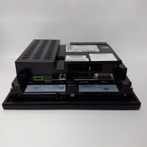
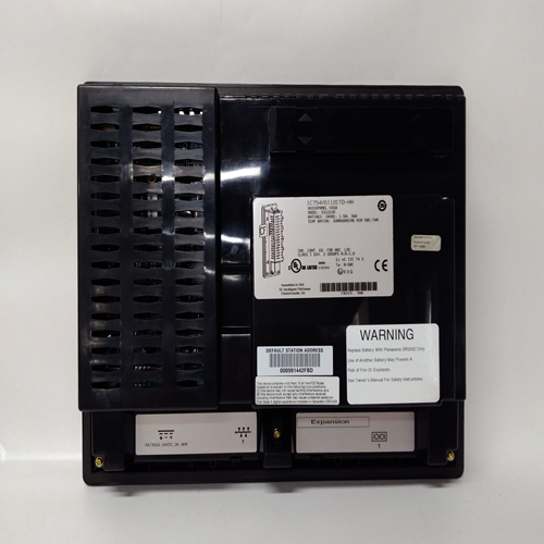
IC754VSI12VTD燃機觸摸屏
1.如果傳感器局部接地,則接地螺柱或穿過傳感器外殼或安裝件,以避免接地回路
電纜的屏蔽護套只能在以下位置連接:一端。即在傳感器處或在接口/中繼卡處。
2.Optima模擬輸出為非隔離輸出,出廠配置為電流宿或電流源。實際情況配置由Optima white上的標簽標識4-20mA輸出引線。三線控制卡電流源、變送器電流接收器連接
Searchpoint Optima(返回到穩壓+23V電源的信號)
單通道控制卡4-20mA 05701-A-0301
配備4-20mA傳感器驅動器05701-A-0283
輸出連接
14.1繼電器輸出注:1.故障繼電器永久配置為正常
在非故障條件下通電運行。
2.除非安裝了高完整性繼電器卡,否則禁止
繼電器(如安裝)永久配置為正常非禁止條件下的斷電操作。
3.報警繼電器可配置為正常通電或正常斷電操作。參考
配置打印輸出或使用的繼電器屏幕確定配置的工程接口軟件。
注意安全
當交流電源連接到繼電器觸點時:
a、 交流電源應最大熔斷5A。
b、 應將安全接地連接至地面中繼卡的終端。
有四種繼電器卡類型,提供不同級別的報警繼電器能力(見第2章第5節)。
繼電器的電纜應盡可能遠離傳感器電纜,尤其是那些承載主電源的電纜。這個
下圖顯示了繼電器觸點連接,如上所示
接線板
報警繼電器可配置為正常斷電或正常通電操作。檢查提供的配置表
利用系統確定繼電器的工作模式
每個信道。繼電器的通電模式可以重新配置
輕松使用連接到工程端口的計算機。聯系Zellweger Analytics或您當地的代理商了解更多信息。顯示觸點位置的斷電和通電繼電器
Note: 1. Where a sensor is earthed locally, either to the Earth Stud or
through the sensor casing or mounting, to avoid earth loops
the screen sheath of the cable should only be connected at
one end. ie. At the sensor or at the Interface/relay Card.
2. The Optima analogue output is non isolated and is factory
configured as current sink or current source. The actual
configuration is identified by a label on the Optima white
4 - 20mA output lead. Three Wire Control Card Current Source, Transmitter Current Sink Connection for
Searchpoint Optima (Signal Returned to Regulated +23V Supply)
Single Channel Control Card 4 - 20mA 05701-A-0301
Fitted with 4 - 20mA Sensor Drive 05701-A-0283
OUTPUT CONNECTIONS
14.1 Relay Outputs
Note: 1. The FAULT relay is permanently configured for normally
ENERGISED operation in the non-fault condition.
2. Unless the High Integrity Relay Card is fitted, the INHIBIT
relay (where fitted) is permanently configured for normally
DE-ENERGISED operation in the non-inhibit condition.
3. The Alarm relays may be configured for either normally
energised or normally de-energised operation. Refer to the
configuration printout or use the relays screen of the
Engineering Interface Software to determine the configuration.
CAUTION
When mains ac is connected to the relay contacts:
a. The ac supply should be fused at 5A maximum.
b. A safety earth connection should be made to the ground
terminal of the relay card.
There are four relay card types providing different levels of alarm relay
capability (See Chapter 2 Section 5).
The cabling to the relays should where possible be kept away from the
sensor cabling, especially those cables carrying mains supplies. The
following figure shows the relay contact connections as shown on the
terminal block.
The alarm relays may be configured for either normally de-energised or
normally energised operation. Check the configuration sheet supplied
with the system to determine the operating mode of the relays on
each channel. The energisation mode of the relays can be reconfigured
easily using a computer attached to the Engineering Port. Contact
Zellweger Analytics or your local agent for more information.
De-energised and Energised Relays Showing Contact Positions


