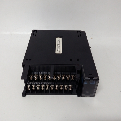
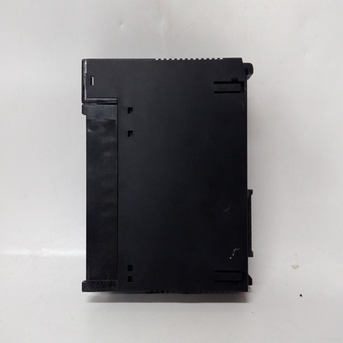
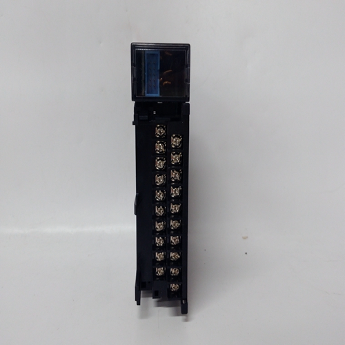
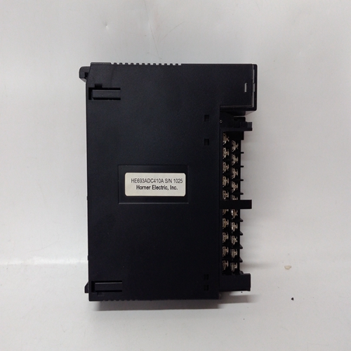
HE693ADC410A燃機電氣模塊
傳感器連接13.1概述
警告傳感器導線連接不正確可能會導致以下部件損壞:傳感器和系統57兩者。
注意安全傳感器必須始終與系統連接57機組處于無動力狀態。在其處隔離電源建立連接前的源代碼。
確保所有外部直流備用電池電源也殘廢重要的
為了確保系統的正確運行,以及滿足歐洲RFI和EMC標準,所有傳感器領域電纜必須屏蔽。每個傳感器的電纜屏蔽應連接至機柜保護接地。根據傳感器的操作,將電纜連接到傳感器并將現場電纜敷設回System 57裝置。這個傳感器電纜應遠離干擾源如交流電力電纜、電機、機械等。
使用隨裝置提供的配置表上的信息以決定將哪個傳感器連接到每個通道。以下章節描述了催化和4-20mA的傳感器連接輸入單通道控制卡。
13.2催化傳感器連接
催化傳感器需要三線連接和傳感器文件將顯示三個連接S、01和NS,它們是通常分別為棕色、白色和藍色。此外,SensePoint可燃ppm版本還具有屏幕連接。
在現場電纜的系統57端,三根傳感器導線應每個都連接到相應的匹配S、01或NS端子連接到所需單體的現場接口或中繼卡
頻道顯示卡傳感器電纜屏蔽或鋼絲鎧裝(或編織物),
應連接到系統(保護)接地。這可能是通過使用金屬電纜,在電纜進入機柜的位置實現
壓蓋,或通過其他合適的方式,并避免任何篩網“尾部”在機柜內。
其中電纜由單獨的屏蔽、護套和電線組成鎧裝(或編織),鎧裝應在機柜處連接
應連接到保護接地和屏蔽護套的入口至現場接口/繼電器卡的接地端子或至適用于儀器接地點。
可燃物傳感器、接線盒和接線盒連接
注:如果傳感器局部接地,則接地螺柱或通過傳感器外殼接地或安裝,為避免接地回路,電纜的屏蔽護套應僅為連接在一端,即在傳感器處或在接口/中繼卡處。
SENSOR CONNECTIONS
13.1 General
WARNING
Incorrect connection of the sensor wires may cause damage to
both the sensor and System 57.
CAUTION
The sensors connections must always be made with the System
57 unit in an unpowered state. Isolate power supplies at their
source before making connections.
Ensure that any external dc backup battery supply is also
disabled.
IMPORTANT
In order to ensure the correct operation of the system and to
meet European Standards for RFI and EMC, all sensor field
cables must be screened. The cable screen of each sensor
should be connected to the cabinet protective earth.
Connect the cabling to sensors in accordance with the Sensor Operating
Instructions and run the field cables back to the System 57 unit. The
sensor cables should be routed away from sources of interference
such as ac power cables, motors, machinery etc.
Use the information on the configuration sheet provided with the unit
to decide which sensor to connect to each channel. The following
sections describe the sensor connections for the Catalytic and 4 - 20mA
input Single Channel Control Cards.
13.2 Catalytic Sensor Connections
Catalytic sensors require a three wire connection and the sensor
documentation will indicate three connections S, 01 and NS, which are
usually brown, white and blue respectively. In addition, the SensePoint
combustible ppm version also has a screen connection.
At the System 57 end of the field cable, the three sensor wires should
each be connected to the respective matching S, 01 or NS terminal on
the Field Interface or Relay Card that is attached to the required Single
Channel Display Card
The sensor cable screen or steel wire armour (or braid), as appropriate,
should be connected to the system (protective) earth. This can be
achieved where the cable enters the cabinet by using a metal cable
gland, or by other suitable means, and avoiding any screen 'tails'
within the cabinet.
Where the cable consists of a separate screen sheath and wire
armour (or braid), the armour should be connected, at the cabinet
entry, to the protective earth and the screen sheath should be connected
to the GROUND terminal of the Field Interface/Relay Card or to a
suitable instrument earth point.
Combustible Sensor, Junction Box and Terminal Block Connections
Note: Where a sensor is earthed locally, either to the Earth Stud or through the sensor casing
or mounting, to avoid earth loops the screen sheath of the cable should only be
connected at one end, i.e., at the sensor or at the Interface/Relay Card.


