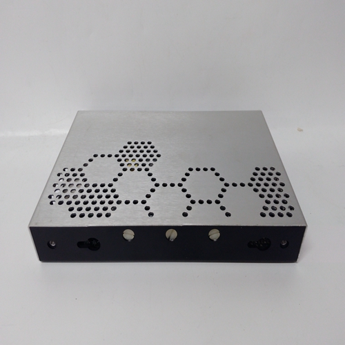
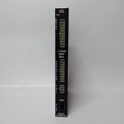
AVS-1700-ACX工控自動(dòng)化模塊
注:安裝支架最多可接受直徑為10mm的螺釘。
(5) 使用適當(dāng)?shù)陌惭b螺釘將機(jī)柜固定到位。
(6) 安裝System 57機(jī)架和AC至DC電源單元(如果所需)插入所示位置的機(jī)柜中。
(7) 將電纜穿過與現(xiàn)場接線板相鄰的壓蓋,在可能的情況下,保持傳感器電纜與其他接線。
(8) 準(zhǔn)備并將電纜端連接至現(xiàn)場接口和繼電器卡終端留有足夠的電纜長度,以便機(jī)架如果未來需要擴(kuò)展,則撤回。用于終端標(biāo)識(shí)見第2章。
(9) 確保機(jī)柜通過連接適當(dāng)?shù)慕拥仉娎|至位于底部面板中的接地螺柱內(nèi)閣
(10) 關(guān)閉并鎖定機(jī)柜。
注意安全
在調(diào)試之前,不要向系統(tǒng)57通電已閱讀并理解程序。參見第5節(jié)面板安裝
所有機(jī)架和交流至直流電源裝置均適用于面板安裝和安裝如下:
(1) 切出合適的孔以容納System 57機(jī)架以及使用尺寸的電源裝置(如需要)
展示:尺寸為(mm)的機(jī)架臺(tái)將機(jī)架插入孔中,并使用M6或類似工具固定螺栓,穿過前法蘭上的四個(gè)安裝孔盤子。
(3) 確保后檢修架后部有足夠的支撐。
(4) 準(zhǔn)備并將電纜端連接至現(xiàn)場接口和繼電器卡和終端。終端標(biāo)識(shí)見第2章,其中可以將傳感器電纜與其他接線分開。
(5) 確保機(jī)架通過連接適當(dāng)?shù)慕拥仉娎|至機(jī)架后部的接地螺柱。機(jī)架安裝
16路3U高后通道和6U高前通道機(jī)架為:
適用于安裝在標(biāo)準(zhǔn)19英寸(483mm)寬的安裝框架中。
其安裝如下:
(1) 將機(jī)架插入19”安裝框架,并使用M6或
穿過前部四個(gè)安裝孔的類似螺栓法蘭盤。
(2) 確保后檢修架后部有足夠的支撐。
(3) 準(zhǔn)備并將電纜端連接至現(xiàn)場接口和繼電器卡終端。終端標(biāo)識(shí)見第2章,其中可以將傳感器電纜與其他接線分開。
(4) 確保機(jī)架通過連接適當(dāng)?shù)慕拥仉娎|至機(jī)架后部的接地螺柱。
Note: The mounting brackets will accept up to a 10mm diameter screw.
(5) Secure the cabinet in position using appropriate mounting screws.
(6) Fit the System 57 Rack and AC to DC Power Supply Unit (if
required) into the cabinet in the positions shown.
(7) Pass cables through the gland adjacent to field terminal blocks,
where possible keeping the sensor cable(s) separate from the
other wiring.
(8) Prepare and connect the cable ends to Field Interface and Relay
Card terminals leaving sufficient cable length to allow for the rack to
be withdrawn if future expansion is required. For terminal
identification see Chapter 2.
(9) Ensure that the cabinet is properly earthed by connecting a suitable
earth cable to the earth stud located in the bottom panel of the
cabinet.
(10) Close and lock the cabinet.
CAUTION
Do not apply power to the System 57 until the commissioning
procedure has been read and understood. See Section 5.PANEL INSTALLATION
All racks and the AC to DC Power Supply Units are suitable for panel
installation and are installed as follows:
(1) Cut out a suitable aperture to accommodate the System 57 rack
and power supply unit (where required) using the dimensions
shown:
Rack Table of Sizes (mm)Insert the rack into the aperture and secure using M6, or similar
bolts, through the four mounting holes located upon the front flange
plates.
(3) Ensure adequate support at the rear of rear access racks.
(4) Prepare and connect the cable ends to Field Interface and Relay
Cards terminals. For terminal identification see Chapter 2. Where
possible keep sensor cables separate from the other wiring.
(5) Ensure that the rack is properly earthed by connecting a suitable
earth cable to the earth stud located at the rear of the rack.
RACK INSTALLATION
The 16-way 3U high rear access and 6U high front access racks are
suitable for mounting in standard 19" (483mm) wide Mounting Frames.
These are fitted as follows:
(1) Insert the rack into the 19" Mounting Frame and secure using M6 or
similar bolts through the four mounting holes located on the front
flange plates.
(2) Ensure adequate support at the rear of rear access racks.
(3) Prepare and connect the cable ends to Field Interface and Relay
Card terminals. For terminal identification see Chapter 2. Where
possible keep sensor cables separate from the other wiring.
(4) Ensure that the rack is properly earthed by connecting a suitable
earth cable to the earth stud located at the rear of the rack.


