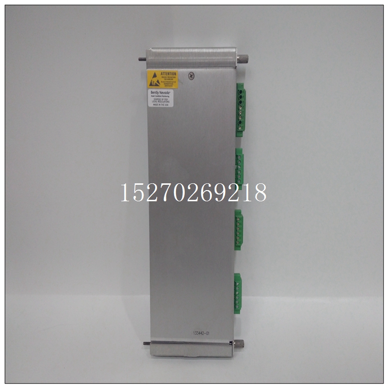
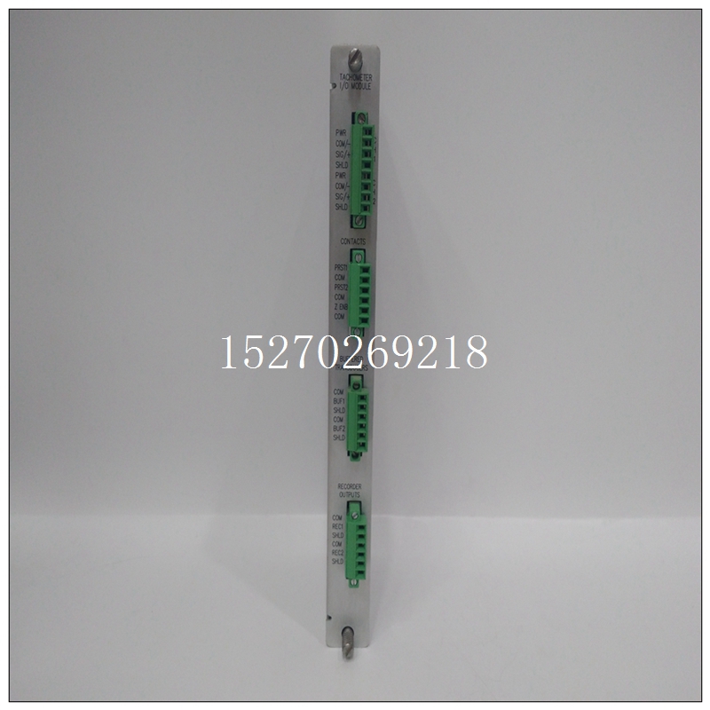
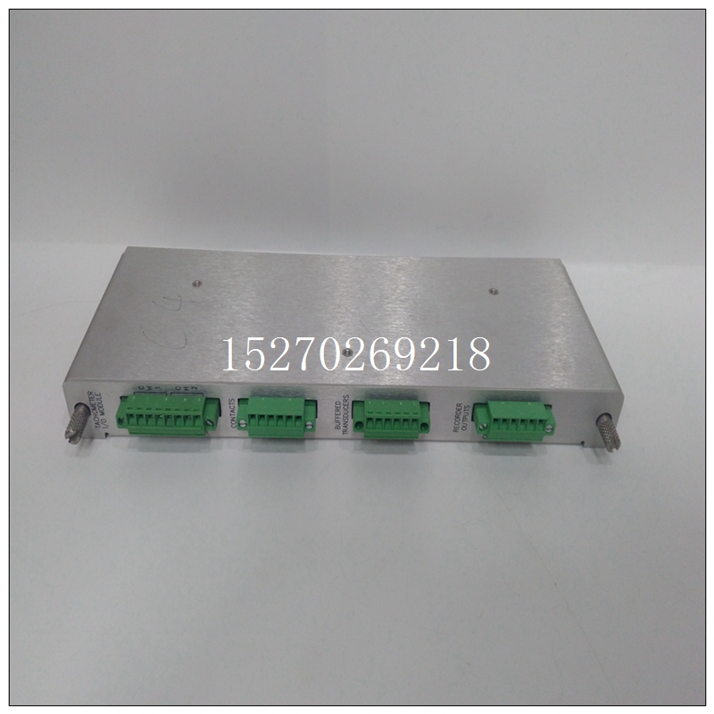
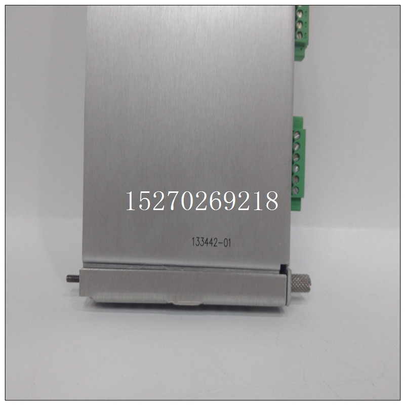
BENTLY 133442-01監測器卡件
車廂溫度傳感器使風扇運行并通過無線連接發出列車溫度和狀態信號。這是RECOM的一款緊湊型8W DC/DC轉換器(32 x 20 x 10mm),輸入范圍為43V至160V,為傳感器提供隔離穩壓電源,同時具有反極性保護和輸出電壓保持功能。根據EN 50121-3-2(軌道交通電磁兼容性標準),DC/DC已經具有很好地EMC性能,但在設計中可以在輸入端增加額外的EMI濾波器來達到低傳導發射和提高瞬態抗干擾能力。在110V系統中高達385V/20ms。由于源阻抗僅為0.2歐姆,簡單地用瞬態電壓抑制器限制輸入電壓會損耗太多功率并且會損壞輸入保險絲或TVS。

BENTLY 133442-01監測器卡件解決方案是使用預穩壓器(圖3)將浪涌電壓抑制到預設的最大值。RECOM提供20W、150W或300W三種DC/DC轉換器模塊。鐵路傳感應用中的DC/DC轉換器可能受到沖擊、振動、溫度和濕度的極端影響。設備的安裝位置決定了使用的類別和等級,這些都在EN 61373標準中有清楚定義。大部份的DC/DC電源會安裝在相對良好的1類B級的環境之中(安裝在車廂機柜內),但仍可能需要額外的加固和封裝。設備使用壽命約20年因此必須通過全面的電性能、HALT、溫度循環和高溫老化等測試來對可靠性進行徹底的確認和驗證。由于110VDC是一種 “不安全” 的電壓,因此轉換器還必須具有通過認證的加強絕緣以防止在二次連接時遭受電擊。
提供合格的現有解決方案
]擁有許多符合EN 50155標準的DC/DC轉換器或完整的鐵路解決方案,提供低功率(8W-240W)至高達2kW的定制模塊,多種輸入電壓范圍涵蓋所有鐵路標稱值,包括16-160V超寬輸入范圍。
憑借長期的鐵路應用經驗,公司還可以提供全面的技術支持、詳細的EMC評估和環境合規報告。PCS提供板卡式安裝以及板卡和機架式產品以滿足客制化的需求,RECOM則專注于PCB安裝低功率DC/DC模塊和參考設計,包括符合EN 50121-3-2標準24-48V或72-110V DC標稱輸入電壓轉換器的EMI濾波電路(參考設計分別為R-REF04-RIA12-1和R-REF04-RIA12-2)。
鐵路級DC/DC轉換器和電源提供一種簡單且經濟高效的途徑,可將低功率傳感和遙測技術融入現有的鐵路車輛和新設計之中,從而協助實現鐵路界的IoT。電磁干擾(EMI)始終是開關電源(AC/DC和DC/DC轉換器)的潛在問題。如今的電源有很好的電磁發射和抗干擾的能力。但為了滿足特定的應用要求,仍要有正確的濾波電路以確保滿足標準的要求。
USB power supply demand power supply current 100mA.
3.3V demand: the main system is calculated according to 3.3v/200ma.
② Power supply demand of communication interface:
Main M-BUS: there are 2 channels in total, each with 128 meters, and the power is about 20W.
From M-BUS: the power supply from the MBus chip is drawn from the MBus bus. The power supply of the isolation optocoupler can be taken from the MBus chip, so there is no need for additional power supply from the MBus circuit.
2-way 485 power supply: the power is about 0.5W.
External power supply 12V: the load capacity is not less than 1a. This power supply is grounded together with the main M-BUS power supply and does not work at the same time. Introduction to power supply scheme: as shown in Figure 3 above, the left side supplies power to the main control system. Among them, the power supply of MCU and USB port is provided after voltage reduction by using the self built step-down scheme; The power supply of the uplink and downlink


