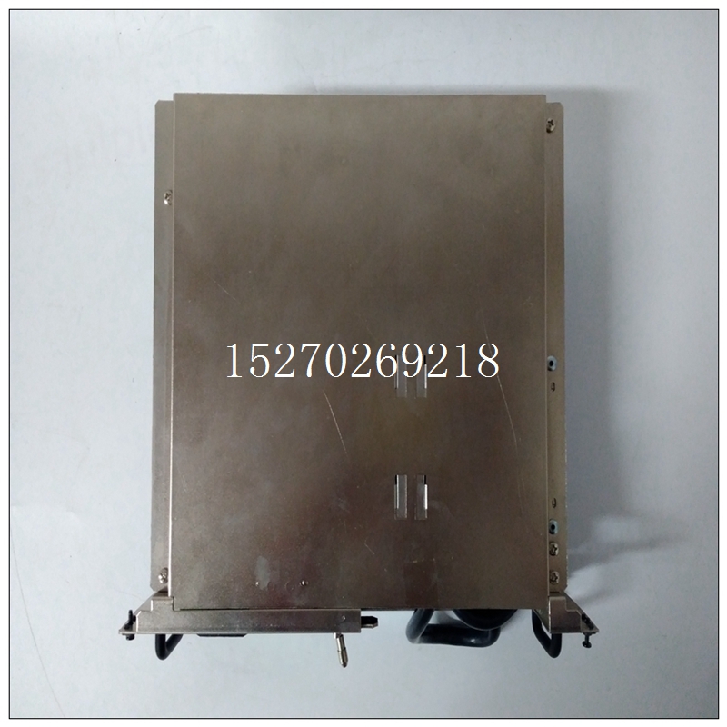
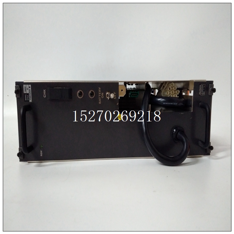
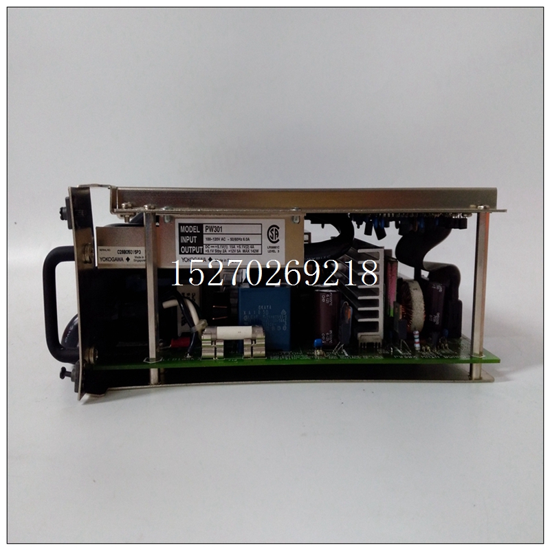
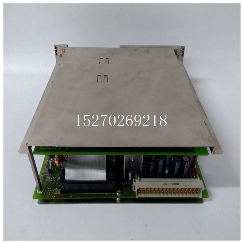
YOKOGAWA PW301模塊,產(chǎn)品重量
VMIC產(chǎn)品上組裝的一些組件可能對靜電放電敏感,可能會對電路板造成損壞受到高能靜電場的影響。未使用的電路板應(yīng)存放在與裝運時相同的保護箱中。當將板放置在工作臺上進行配置等,建議將導電材料插入電路板下方,以提供導電性移走收到后,在運輸集裝箱內(nèi)發(fā)現(xiàn)的任何預(yù)防措施應(yīng)觀察。所有物品應(yīng)仔細打開包裝,并徹底檢查裝運期間可能發(fā)生的損壞。
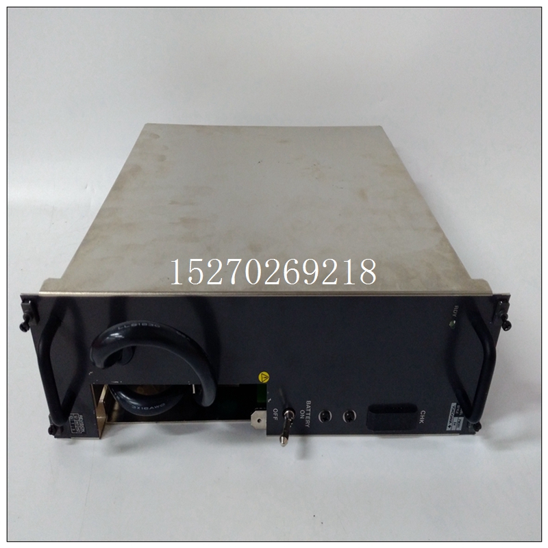
YOKOGAWA PW301模塊應(yīng)檢查電路板對于損壞的組件、損壞的印刷電路板、熱損壞和其他可見污染。因運輸損壞引起的所有索賠應(yīng)提交給承運人和發(fā)送給VMlC的完整報告以及咨詢請求關(guān)于受損物品的處置。5.1.1開關(guān)和跳線位置參考圖5-1,了解本節(jié)所述開關(guān)和跳線的位置部分5.2物理安裝注意:通電時不要安裝或拆卸電路板。斷開設(shè)備電源,將電路板插入機箱,同時確保卡在支架中正確對齊和定向卡片導向器。將卡平穩(wěn)地向前滑動到配對連接器上,直至牢固就坐的。5.3地址修飾符VMIVME-2511在工廠配置為響應(yīng)短路監(jiān)控I10通道通過安裝跳線J9來啟用電路板,可以更改此配置響應(yīng)短的非特權(quán)I10訪問。5.4跳線配置和詳細的I10配置以下方框圖顯示了上可用的詳細跳線選項VMIVME-2511。方框圖參考P1/T#I.跳線定義表5-1除了定義一些未定義的跳線外,還詳細解釋了每個跳線的功能如圖5-2所示*注1:這四個跳線僅用于緩沖I10選項。**注2:與支架配對的跳線相互排斥。如果其中一個跳線線對已安裝,不得安裝線對中的其他跳線,否則可能導致?lián)p壞
連接至VMIVME-2511或連接至VMIVME-2511的現(xiàn)場電子設(shè)備。
Some of the components assembled on VMIC's products may be
sensitive to electrostatic discharge and damage may occur on boards
that are subjected to a high energy electrostatic field. Unused boards
should be stored in the same protective boxes as shipped. When the
board is to be laid on a bench for configuring, etc., it is suggested that
conductive material be inserted under the board to provide a conductive
shunt.
Upon receipt, any precautions found in the shipping container should be
observed. All items should be carefully unpacked and thoroughly inspected for
damage that might have occurred during shipment. The board(s) should be checked
for broken components, damaged printed-circuit board(s), heat damage, and other
visible contamination. All claims arising from shipping damage should be filed with the
carrier and a complete report sent to VMlC together with a request for advice
concerning disposition of the damaged item(s).
5.1.1 SWITCH AND JUMPER LOCATIONS
Refer to Figure 5-1 for the locations of the switches and jumpers described in this
section.
5.2 PHYSICAL INSTALLATION
CAUTION: Do not install or remove boards while power is applied.
Deenergize the equipment and insert the board into an appropriate slot of the
chassis, while ensuring that the card is properly aligned and oriented in the supporting
card guides. Slide the card smoothly forward against the mating connector until firmly
seated.
5.3 ADDRESS MODIFIERS
The VMIVME-2511 is configured at the factory to respond to short supervisory I10
access. This configuration can be changed by installing jumper J9 to enable the board
to respond to short non-privileged I10 access.
5.4 JUMPER CONFIGURATION AND DETAILED I10 CONFIGURATION
The following block diagrams show the detailed jumpering options available on
the VMIVME-2511. The block diagrams reference P1/T #I. Jumper Definition Table 5-1
explains the function of each jumper in detail, in addition to defining some jumpers not
shown in Figure 5-2* NOTE 1 : These four jumpers are used only on the buffered I10 Option.
** NOTE 2: Jumpers paired with brackets are mutually exclusive. If one of the jumper
pairs is installed, the other jumper in the pair must not be installed or damage may result
to the VMIVME-2511 or to field electronics connected to the VMIVME-2511.


